2D Constraint Solving
Constraint Element Types
Constraint element types include: points, line segments, circles, circular arcs, ellipses, elliptical arcs, parabolic arcs, hyperbolic arcs, and B-spline curves. Below, we will introduce the creation methods for these constraint elements.
Point
The wrapper for GCSSystem.
Definition AMCAXGCS.h:352
Point2d GetPoint2d(const GCSWVarGeomHandle &h) const
Get point.
Status Create2dPoint(GCSWVarGeomHandle &h, const Point2d &point)
Create a point in 2D.
The wrapper for GCSVarGeomHandle.
Definition AMCAXGCS.h:268
Point in 2d.
Definition AMCAXGCS.h:127
After creation, it supports updating point:
Status UpdatePoint2d(const GCSWVarGeomHandle &h, const Point2d &point)
Update point in 2d.
Status
Enumeration of GCSSystem status.
Definition AMCAXGCS.h:237
Line Segment
gcsSystem.
Create2dLine(handleLine, handlePoint1, handlePoint2);
Status Create2dLine(GCSWVarGeomHandle &h, const GCSWVarGeomHandle &point0, const GCSWVarGeomHandle &point1)
Create a line segment in 2D.
Line2d GetLine2d(const GCSWVarGeomHandle &h) const
Get line.
Line in 2d.
Definition AMCAXGCS.h:143
Circle
Circles are defined by the following core parameters:
- Center (center): c
- Radius (radius): r
double radius = 2.0;
Circle2d GetCircle2d(const GCSWVarGeomHandle &h) const
Get circle.
Status Create2dCircle(GCSWVarGeomHandle &h, const GCSWVarGeomHandle ¢er, double radius)
Create a circle in 2D.
Circle in 2d.
Definition AMCAXGCS.h:153
After creation, it supports updating circle:
double radius_update = 3.0;
Status UpdateCircle2d(const GCSWVarGeomHandle &h, const Point2d ¢er, double radius)
Update circle in 2d.
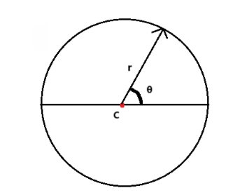
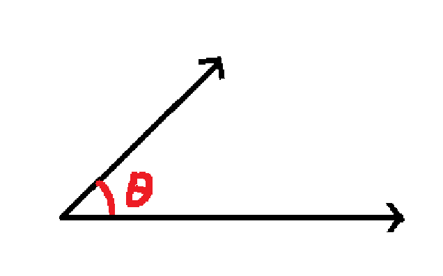
Circular Arc
To represent the range of a circular arc, two parameters are introduced:
- Start angle (thetaStart): Position of the arc's starting point in the circle's parametric representation
- Angle range (thetaRange): Range of the arc in the circle's parametric representation
If thetaRange > 0, the arc is counterclockwise, θ∈[thetaStart, thetaStart + thetaRange]; if thetaRange < 0, the arc is clockwise, θ∈[thetaStart + thetaRange, thetaStart].
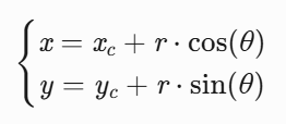
The coordinates of any point P on the arc can be obtained through polar coordinate conversion:
gcsSystem.
Create2dArc(handleArc, handleCenter, handleArcstart, handleArcend, range);
Status Create2dArc(GCSWVarGeomHandle &h, const GCSWVarGeomHandle ¢er, const GCSWVarGeomHandle &start, const GCSWVarGeomHandle &end, double range=0)
Create an arc in 2D.
Arc2d GetArc2d(const GCSWVarGeomHandle &h) const
Get arc.
constexpr double half_pi
pi/2
Definition Constants.hpp:50
Arc of circle in 2d.
Definition AMCAXGCS.h:161
Note: When creating an arc, the parameter range specifies the arc's extent. If not specified, range defaults to 0, and the solver will calculate the range in a counterclockwise direction.
Ellipse
Ellipses are defined by the following core parameters:
- Center (center): c
- Major axis (majorAxis)
- Minor axis (minorAxis)
- Major radius (majorRadius)
- Minor radius (minorRadius)
double majorRadius = 2.0;
double minorRadius = 1.0;
gcsSystem.
Create2dEllipse(handleEllipse, handleCenter, majorAxis, majorRadius, minorAxis, minorRadius);
Ellipse2d GetEllipse2d(const GCSWVarGeomHandle &h) const
Get ellipse.
Status Create2dEllipse(GCSWVarGeomHandle &h, const GCSWVarGeomHandle ¢er, const Vector2d &majorAxis, double majorRadius, const Vector2d &minorAxis, double minorRadius)
Create an ellipse in 2D.
Ellipse in 2d.
Definition AMCAXGCS.h:171
Vector in 2d.
Definition AMCAXGCS.h:135
After creation, it supports updating ellipse:
double majorRadius_update = 3.0;
double minorRadius_update = 2.0;
Status UpdateEllipse2d(const GCSWVarGeomHandle &h, const Point2d ¢er, const Vector2d &majorAxis, double major, double minor)
Update ellipse in 2d.
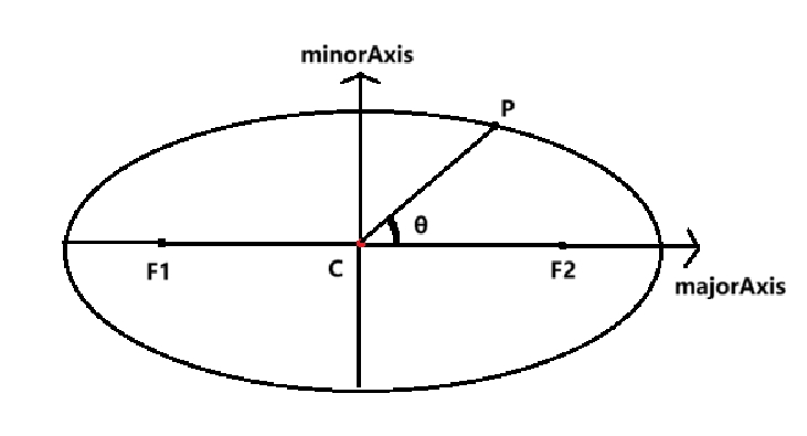
Elliptical Arc
To represent the range of an elliptical arc, two parameters are introduced:
- Start angle (thetaStart): Position of the elliptical arc's starting point in the circle's parametric representation
- Angle range (thetaRange): Range of the elliptical arc in the circle's parametric representation
If thetaRange > 0, the elliptical arc is counterclockwise, θ∈[thetaStart, thetaStart + thetaRange]; if thetaRange < 0, the elliptical arc is clockwise, θ∈[thetaStart + thetaRange, thetaStart].
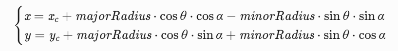
The coordinates of any point P on the elliptical arc can be obtained through polar coordinate conversion:
- Calculate the major axis angle α (angle between major axis and x-axis)
α = atan2(majorAxis.y, majorAxis.x)
double majorRadius = 2.0;
double minorRadius = 1.0;
gcsSystem.
Create2dArcOfEllipse(handleArcOfEllipse, handleCenter, majorAxis, majorRadius, minorAxis, minorRadius, handleArcOfEllipsestart, handleArcOfEllipseend, range);
ArcOfEllipse2d GetArcOfEllipse2d(const GCSWVarGeomHandle &h) const
Get arc of ellipse.
Status Create2dArcOfEllipse(GCSWVarGeomHandle &h, const GCSWVarGeomHandle ¢er, const Vector2d &majorAxis, double majorRadius, const Vector2d &minorAxis, double minorRadius, const GCSWVarGeomHandle &start, const GCSWVarGeomHandle &end, double range=0)
Create an arc of ellipse in 2D.
Arc of ellipse in 2d.
Definition AMCAXGCS.h:182
Note: When creating an elliptical arc, the parameter range specifies the arc's extent. If not specified, range defaults to 0, and the solver will calculate the range in a counterclockwise direction.
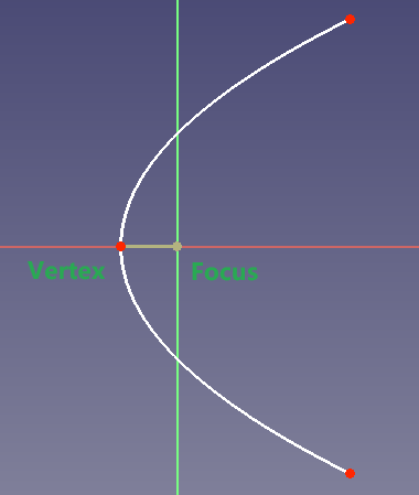
Parabolic Arc
Parabolic arcs are defined by the following core parameters:
- Focus (focus): f
- Vertex (vertex): v
- paramStart: Vertical coordinate of the arc's starting point in the parabola's local coordinate system
- paramEnd: Vertical coordinate of the arc's ending point in the parabola's local coordinate system
AMCAX::GCS::GCSWVarGeomHandle handleArcOfParabola, handleArcOfParabolafocus, handleArcOfParabolavertex, handleArcOfParabolastart, handleArcOfParabolaend;
gcsSystem.
Create2dArcOfParabola(handleArcOfParabola, handleArcOfParabolafocus, vertex, handleArcOfParabolastart, handleArcOfParabolaend);
Status Create2dArcOfParabola(GCSWVarGeomHandle &h, const GCSWVarGeomHandle &focus, const Point2d &vertex, const GCSWVarGeomHandle &start, const GCSWVarGeomHandle &end)
Create an arc of parabola in 2D.
ArcOfParabola2d GetArcOfParabola2d(const GCSWVarGeomHandle &h) const
Get arc of parabola.
Arc of parabola in 2d.
Definition AMCAXGCS.h:195
After creation, it supports updating parabolic arc:
Status UpdateParabola2d(const GCSWVarGeomHandle &h, const Point2d &vertex, const Point2d &focus)
Update parabola in 2d.
Hyperbolic Arc
Hyperbolic arcs are defined by the following core parameters:
- Focus (focus)
- Hyperbola center (center)
- Major radius (majorRadius)
- paramStart: Vertical coordinate of the arc's starting point in the hyperbola's local coordinate system
- paramEnd: Vertical coordinate of the arc's ending point in the hyperbola's local coordinate system
AMCAX::GCS::GCSWVarGeomHandle handleArcOfHyperbola, handleArcOfHyperbolaCenter, handleArcOfHyperbolaFocus, handleArcOfHyperbolaStart, handleArcOfHyperbolaEnd;
double majorRadius = 1.0;
gcsSystem.
Create2dArcOfHyperbola(handleArcOfHyperbola, handleArcOfHyperbolaCenter, handleArcOfHyperbolaFocus, majorRadius, handleArcOfHyperbolaStart, handleArcOfHyperbolaEnd);
Status Create2dArcOfHyperbola(GCSWVarGeomHandle &h, const GCSWVarGeomHandle ¢er, const GCSWVarGeomHandle &focus, double majorRadius, const GCSWVarGeomHandle &start, const GCSWVarGeomHandle &end)
Create an arc of hyperbola in 2D.
ArcOfHyperbola2d GetArcOfHyperbola2d(const GCSWVarGeomHandle &h) const
Get arc of hyperbola.
Arc of hyperbola in 2d.
Definition AMCAXGCS.h:205
After creation, it supports updating hyperbolic arc:
double majorRadius_update = 2.0;
Status UpdateHyperbola2d(const GCSWVarGeomHandle &h, const Point2d ¢er, const Point2d &focus, double major)
Update hyperbola in 2d.
B-Spline Curve
To construct a non-periodic B-spline curve, you can use Create2dBSplineCurve.
Non-Rational
std::vector<AMCAX::GCS::GCSWVarGeomHandle> handleControlPoints;
std::vector<AMCAX::GCS::Point2d> controlPoints{
{0.5, 0.5},
{1.0, 3.0},
{3.0, 1.0},
{3.8,2.0},
{2.5,3.5},
{1.0,0.5},
{0.3,2.0} };
handleControlPoints.push_back(handlePoint);
}
int degree = 5;
std::vector<double> knotSequence{ 0.,0., 0.25, 0.5,0.75,1.,1.25,1.5,2.,2. ,2.,2.,2. };
Status Create2dBSplineCurve(GCSWVarGeomHandle &h, const std::vector< GCSWVarGeomHandle > &controlPoints, const std::vector< double > &knotSequence, int degree)
Create a non-rational B-spline curve in 2D.
BSplineCurve2d GetBSplineCurve2d(const GCSWVarGeomHandle &h) const
Get b-spline curve.
B-spline curve in 2d.
Definition AMCAXGCS.h:216
To construct a non-periodic, non-rational B-spline curve with a fixed degree of 3, you can use Create2dCubicBSplineCurve.
std::vector<AMCAX::GCS::GCSWVarGeomHandle> handleControlPoints;
std::vector<AMCAX::GCS::Point2d> controlPoints{
{0.,0.},
{1.,1.},
{2.,2.},
{3.,-5.},
{0.,0.} };
handleControlPoints.push_back(handlePoint);
}
std::vector<double> knotSequence{ 0.,0., 0.25, 0.5,0.75,1.,1.,1.,1. };
Status Create2dCubicBSplineCurve(GCSWVarGeomHandle &h, const std::vector< GCSWVarGeomHandle > &controlPoints, const std::vector< double > &knotSequence)
Create a non-rational cubic B-spline curve in 2D.
Rational
std::vector<AMCAX::GCS::GCSWVarGeomHandle> handleControlPoints;
std::vector<AMCAX::GCS::Point2d> controlPoints{
{0., 0.},
{1., 1.},
{2., 2.},
{3.,-5.} };
handleControlPoints.push_back(handlePoint);
}
std::vector<double> weights = { 1., 2., 1., 1. };
std::vector<double> knots = { 1., 2., 3., 4. };
std::vector<int> multiplicities = { 2, 2, 2, 2 };
int degree = 3;
Note: Regardless of the construction method, the following B-spline characteristics must be satisfied:
- 1.Satisfy m = n + p + 1 and p ≥ n + 1 (where m is the number of knot vectors, n is the curve degree, and p is the number of control points)
- 2.Knot vectors must be non-decreasing
- 3.The repetition count of the first and last knot vectors must not exceed n + 1, and the repetition count of intermediate knot vectors must not exceed n
Update
The UpdateBSpline2d function enables the update of core parameters of a B-spline curve (including control points, knot vectors, knot multiplicities, and curve degree), and also supports the update of weight parameters. Specific usage examples are as follows:
Basic Parameter Update (Without Weights)
std::vector<AMCAX::GCS::GCSWVarGeomHandle> handleControlPoints, handleControlPoints_update;
int degree = 1;
std::vector<AMCAX::GCS::Point2d> controlPoints{
{1.13, 4.1},
{1.63, 4.8},
{2.13, 5.2},
{2.63, 5.0} };
handleControlPoints.push_back(handlePoint);
}
std::vector<double> flatKnots;
for (int i = 0; i < controlPoints.size() + degree + 1; i++)
{
flatKnots.push_back(i);
}
std::vector<AMCAX::GCS::Point2d> controlPoints_update
{
{1.,12.},
{2.,2.431},
{1.3421,5.123},
{2.432153,12.432},
{4.3421,1.321},
{3.123,83.10},
{1.0546,1.112},
{1.65,8.130},
{8.23,53.01},
{15,2.13}
};
handleControlPoints_update.push_back(handlePoint_update);
}
int degree_update = 2;
std::vector<double> flatKnots_update;
std::vector<int> multiplicities_update;
for (int i = 0; i < controlPoints_update.size() + degree_update + 1; i++) {
flatKnots_update.push_back(i);
multiplicities_update.push_back(1);
}
Status UpdateBSpline2d(GCSWVarGeomHandle &h, const std::vector< GCSWVarGeomHandle > &controlPoints, const std::vector< double > &knots, const std::vector< int > &multiplicities, int degree)
Update bspline curve in 2d.
Parameter Update with Weights
std::vector<AMCAX::GCS::GCSWVarGeomHandle> handleControlPoints, handleControlPoints_update;
std::vector<AMCAX::GCS::Point2d> controlPoints{
{1.13, 4.1},
{1.63, 4.8},
{2.13, 5.2},
{2.63, 5.0},
{3.13, 4.3},
{3.63, 3.9},
{4.13, 4.2},
{4.63, 4.9},
{5.13, 5.4},
{5.63, 5.1}
};
handleControlPoints.push_back(handlePoint);
}
std::vector<double> weights = { 1.0, 1.5, 0.8, 1.2, 0.9, 1.1, 1.3, 0.7, 1.4, 1.0 };
int degree = 3;
std::vector<double> flatKnots;
std::vector<int> multiplicities;
for (int i = 0; i < controlPoints.size() + degree + 1; i++) {
flatKnots.push_back(i);
multiplicities.push_back(1);
}
std::vector<AMCAX::GCS::Point2d> controlPoints_update
{
{0.0, 0.0},
{2.0, 3.0},
{4.0, 3.0},
{6.0, 0.0}
};
handleControlPoints_update.push_back(handlePoint_update);
}
int degree_update = 2;
std::vector<double> weights_update = { 1.0, 1.5, 0.8, 1.0 };
std::vector<double> flatKnots_update = { 0.0, 1.0, 2.0 };
std::vector<int> multiplicities_update = { 3, 1, 3 };
AMCAX::GCS::Status status = gcsSystem.
UpdateBSpline2d(handleBspline, handleControlPoints_update, weights_update, flatKnots_update, multiplicities_update, degree_update);
Conic Sections
A conic section is defined as the intersection curve of a cone and a plane, which can be represented by a NURBS curve. Its core defining parameters include three control points and one shape factor, and the specific functions of each parameter are as follows:
1. Control Points
The three control points of a conic section are P1, P2, and P3 respectively, and their respective functions and geometric roles are as follows:
- P1: Starting point of the curve
- P2: Middle control point of the curve (usually not on the curve), used to control the direction and shape of the curve
- P3: End point of the curve
Geometric Roles of Control Points:
- P1 and P3 together define the two endpoints of the conic section, limiting the start and end range of the curve;
- P2 is the shoulder point. The line segments P1P2 and P2P3 are the tangents of the curve at endpoints P1 and P3 respectively, which directly affect the direction and smoothness of the curve at the endpoints;
- The three control points P1, P2, and P3 can form a control triangle (△P1P2P3).
2. Shape Factor of Conic Section
The shape factor (commonly denoted by ρ) is a key parameter determining the type of conic section, which directly decides whether the curve is ultimately an ellipse, a parabola, or a hyperbola. Its core geometric role is closely related to the weight of the middle control point P2.
Correlation between Shape Factor and Weight of P2:
In the rational Bézier formula, the weight of the middle control point P2 is usually denoted as ω₁. The correlation between the shape factor ρ and ω₁ is generally expressed as ω₁ = ρ / (1 - ρ) (the specific expression can be adjusted according to the actual implementation scenario). The two are mutually mapped and jointly affect the curve shape.
Correspondence between ρ Value and Conic Section Type:
- When 0 < ρ < 0.5: The curve is an elliptic arc; in particular, when P1, P2, and P3 form an isosceles triangle, a circular arc can be accurately represented;
- When ρ = 0.5: The curve is a parabolic arc, and the corresponding rational Bézier curve degenerates into an ordinary (non-rational) quadratic Bézier curve at this time;
- When 0.5 < ρ < 1.0: The curve is a hyperbolic arc.
Boundary Cases: When ρ = 0 or ρ = 1, the conic section degenerates into a line segment (the connecting line between P1 and P3).
The following takes the construction of an elliptic arc as an example:
std::vector< AMCAX::GCS::GCSWVarGeomHandle > handleControlPoints;
handleControlPoints = { handlePoint1, handlePoint2, handlePoint3 };
double rho = 0.3;
ConicCurve2d GetConicCurve2d(const GCSWVarGeomHandle &h) const
Get conic curve.
Status Create2dConicCurve(GCSWVarGeomHandle &h, const std::vector< GCSWVarGeomHandle > &controlPoints, double rho)
Create a conic curve in 2D.
Status Solve()
General solve. Solve the constraint system.
Conic curve in 2d.
Definition AMCAXGCS.h:229
Constraint Types
The types of constraints include horizontal, vertical, orthogonal, parallel, perpendicular, angular, distance, symmetry, equality, attachment, tangency, midpoint, and curve length constraints.
Horizontal Constraint
Create horizontal constraint between two points
After applying a horizontal constraint between two points, their y-coordinates will be the same.
The wrapper for GCSConHandle.
Definition AMCAXGCS.h:328
Status Create2dHorizontal(GCSWConHandle &h, GCSWVarGeomHandle &ln)
Create a 2D horizontal constraint on the line.
Create horizontal distance constraint between two points
After applying a horizontal distance constraint between two points, the difference in their x-coordinates will equal the specified distance.
double dis = 2.0;
Status Create2dHorizontalDist(GCSWConHandle &h, GCSWVarGeomHandle &ln, double d)
Create a 2D horizontal distance constraint between the ends of the line.
Create horizontal constraint between line segment endpoints
After applying a horizontal constraint to a line segment's endpoints, their y-coordinates will be the same.
gcsSystem.
Create2dLine(handleLine, handlePoint1, handlePoint2);
Create horizontal distance constraint between line segment endpoints
After applying a horizontal distance constraint to a line segment's endpoints, the difference in their x-coordinates will equal the specified distance.
gcsSystem.
Create2dLine(handleLine, handlePoint1, handlePoint2);
double dis = 2.0;
Vertical Constraint
Create vertical constraint between two points
After applying a vertical constraint between two points, their x-coordinates will be the same.
Status Create2dVertical(GCSWConHandle &h, GCSWVarGeomHandle &ln)
Create a 2D vertical constraint on the line.
Create vertical distance constraint between two points
After applying a vertical distance constraint between two points, the difference in their y-coordinates will equal the specified distance.
double dis = 2.0;
Status Create2dVerticalDist(GCSWConHandle &h, GCSWVarGeomHandle &ln, double d)
Create a 2D vertical distance constraint between the ends of the line.
Create vertical constraint between line segment endpoints
After applying a vertical constraint to a line segment's endpoints, their x-coordinates will be the same.
gcsSystem.
Create2dLine(handleLine, handlePoint1, handlePoint2);
Create vertical distance constraint between line segment endpoints
After applying a vertical distance constraint to a line segment's endpoints, the difference in their y-coordinates will equal the specified distance.
gcsSystem.
Create2dLine(handleLine, handlePoint1, handlePoint2);
double dis = 2.0;
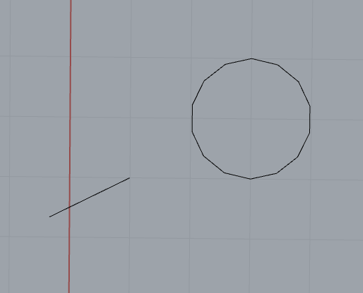
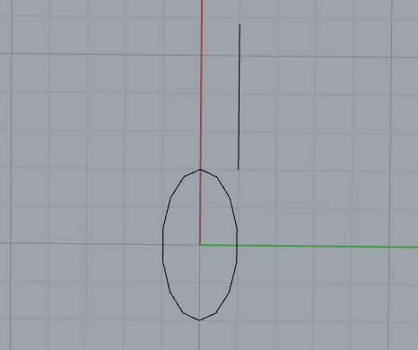
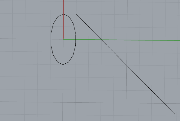
Orthogonal Constraint
Orthogonal constraints can be created between a line segment and a circle (arc)/ellipse (arc)/parabolic arc. After applying the orthogonal constraint, the line segment will remain perpendicular to the tangent of the curve at their intersection point. Taking a line segment and a circle as an example:
gcsSystem.
Create2dLine(handleLine, handlePoint1, handlePoint2);
double radius = 1.0;
Status Create2dNormal(GCSWConHandle &h, GCSWVarGeomHandle &ln, GCSWVarGeomHandle &cur)
Create a 2D normal constraint between line and circle/ellipse/parabola.
The result is shown in the following figure:
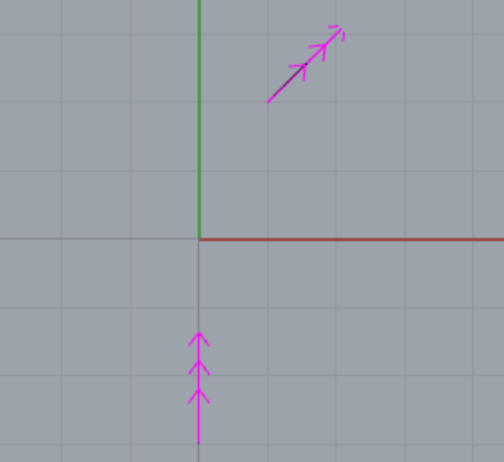
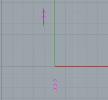
Parallel Constraint
Parallel axial constraints can be created between line segments/ellipses (arcs)/parabolic arcs/hyperbolic arcs. The axial direction of a line segment is the direction of the line segment itself; the axial direction of an ellipse (arc) is the direction of its major axis; the axial direction of a parabola (arc) is the direction of its transverse axis; and the axial direction of a hyperbola (arc) is the direction of its transverse axis.
The following is an example of creating a parallel constraint between a line segment and an ellipse:
gcsSystem.
Create2dLine(handleLine1, handlePoint1, handlePoint2);
double majorRadius = 2.0;
double minorRadius = 1.0;
gcsSystem.
Create2dEllipse(handleEllipse, handleCenter, majorAxis, majorRadius, minorAxis, minorRadius);
Status Create2dParallel(GCSWConHandle &h, GCSWVarGeomHandle &geo1, GCSWVarGeomHandle &geo2)
Create a 2D parallel constraint between two geometries with direction.
After applying the constraint, the line segment will remain parallel to the major axis of the ellipse.The result is shown in the following figure:
Perpendicular Constraint
Axial perpendicular constraints can be created between line segments and line segments/circles (arcs)/ellipses (elliptical arcs)/parabolic arcs. The axial direction of a line segment is the direction of the line segment itself; the axial direction of an ellipse (arc) is the direction of its major axis; the axial direction of a parabola (arc) is the direction of its transverse axis; and the axial direction of a hyperbola (arc) is the direction of its transverse axis.
The following is an example of creating a perpendicular constraint between a line segment and an ellipse:
gcsSystem.
Create2dLine(handleLine1, handlePoint1, handlePoint2);
double majorRadius = 2.0;
double minorRadius = 1.0;
gcsSystem.
Create2dEllipse(handleEllipse, handleCenter, majorAxis, majorRadius, minorAxis, minorRadius);
Status Create2dPerpendicular(GCSWConHandle &h, GCSWVarGeomHandle &geo1, GCSWVarGeomHandle &geo2)
Create a 2D perpendicular constraint between two geometries with direction.
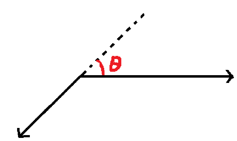
Angle Constraint
Axial Angle Constraint Between Line Segments and Ellipses (Arcs)/Parabolic Arcs/Hyperbolic Arcs
The following is an example of creating an angle constraint between a line segment and an ellipse:
gcsSystem.
Create2dLine(handleLine1, handlePoint1, handlePoint2);
double majorRadius = 2.0;
double minorRadius = 1.0;
gcsSystem.
Create2dEllipse(handleEllipse, handleCenter, majorAxis, majorRadius, minorAxis, minorRadius);
Status Create2dAngVecVec(GCSWConHandle &h, GCSWVarGeomHandle &geo1, GCSWVarGeomHandle &geo2, double a)
Create a 2D angle constraint between two geometries with direction.
constexpr double quarter_pi
pi/4
Definition Constants.hpp:58
After applying the constraint, the included angle between the line segment and the major axis of the ellipse will be the specified angle.The result is shown in the following figure:
Angular constraint on 2D arc
gcsSystem.
Create2dArc(handleArc, handleCenter, handleArcstart, handleArcend, range);
Status Create2dAngArc(GCSWConHandle &h, GCSWVarGeomHandle &arc, double a)
Crate an angle constraint on a 2D arc.
Distance Constraint
Distance constraint between two points
double dis = 2.0;
Status Create2dDistPtPt(GCSWConHandle &h, GCSWVarGeomHandle &pt1, GCSWVarGeomHandle &pt2, double d)
Create a 2D distance point/point constraint.
If dis is set to 0.0, this implements a concentric constraint.
double radius = 2.0;
double majorRadius = 2.0;
double minorRadius = 1.0;
gcsSystem.
Create2dEllipse(handleEllipse, handleCenter_e, majorAxis, majorRadius, minorAxis, minorRadius);
double dis = 0.0;
gcsSystem.
Create2dDistPtPt(HandleDistPtPt, handleCenter_c, handleCenter_e, dis);
Distance constraint between point and line segment
gcsSystem.
Create2dLine(handleLine, handlePoint1, handlePoint2);
double dis = 2.0;
Status Create2dDistPtLn(GCSWConHandle &h, GCSWVarGeomHandle &pt, GCSWVarGeomHandle &ln, double d)
Create a 2D distance point/line constraint.
Distance constraint between two line segments
After applying a distance constraint between two line segments, they will remain parallel and the distance between them will be fixed to the specified value.
gcsSystem.
Create2dLine(handleLine1, handlePoint1, handlePoint2);
gcsSystem.
Create2dLine(handleLine2, handlePoint3, handlePoint4);
double dis = 3.0;
Status Create2dDistLnLn(GCSWConHandle &h, GCSWVarGeomHandle &ln1, GCSWVarGeomHandle &ln2, double d)
Create a 2D distance line/line constraint.
Symmetric Constraint
Symmetric constraint between two points about a line segment
gcsSystem.
Create2dLine(handleLine, handlePoint1, handlePoint2);
Status Create2dSymmPtPtLn(GCSWConHandle &h, GCSWVarGeomHandle &pt1, GCSWVarGeomHandle &pt2, GCSWVarGeomHandle &axis)
Create a 2D point-point symmetric constraint with line.
Symmetric constraint between two line segments about a line segment
AMCAX::GCS::GCSWVarGeomHandle handlePoint1, handlePoint2, handlePoint3, handlePoint4, handlePoint5,handlePoint6, handleLine1, handleLine2, handleLine3;
gcsSystem.
Create2dLine(handleLine1, handlePoint1, handlePoint2);
gcsSystem.
Create2dLine(handleLine2, handlePoint3, handlePoint4);
gcsSystem.
Create2dLine(handleLine3, handlePoint5, handlePoint6);
Status Create2dSymmLnLnLn(GCSWConHandle &h, GCSWVarGeomHandle &ln1, GCSWVarGeomHandle &ln2, GCSWVarGeomHandle &axis)
Create a 2D line-line symmetric constraint with line.
Symmetric constraint between two circles (arcs) about a line segment
After applying a symmetric constraint between two circles (arcs) about a line segment, their centers will be symmetric about the line.
Example with circles:
double radius = 1.0;
gcsSystem.
Create2dLine(handleLine, handlePoint1, handlePoint2);
Status Create2dSymmCirCirLn(GCSWConHandle &h, GCSWVarGeomHandle &cir1, GCSWVarGeomHandle &cir2, GCSWVarGeomHandle &axis)
Create a 2D circle-circle symmetric constraint with line.
Equal Constraint
Supports equal constraints between line segments/line segments, circles(arcs)/circles(arcs), and ellipses(elliptical arcs)/ellipses(elliptical arcs). After applying an equal constraint between line segments, their lengths will be equal; between circles(arcs), their radii will be equal; between ellipses(elliptical arcs), their major and minor radii will be equal.
Example with circles:
double radius1 = 1.0;
double radius2 = 2.0;
gcsSystem.
Create2dEqual(handleEqual, handleCircle1, handleCircle2);
Status Create2dEqual(GCSWConHandle &h, GCSWVarGeomHandle &g1, GCSWVarGeomHandle &g2)
Create a 2D equal constraint between line/line, circle/circle or ellipse/ellipse.
Attachment Constraint
Supports attaching points to line segments, circles (arcs), ellipses (arcs), hyperbolic arcs, parabolic arcs, B-splines, and conic curves.
Example of attaching a point to a circle:
double radius = 1.0;
Status Create2dPtOnObject(GCSWConHandle &h, GCSWVarGeomHandle &pt, GCSWVarGeomHandle &geom)
Create a constraint to attach the point to the object.
Tangent Constraint
Tangent constraint between line segment and circle (arc)
gcsSystem.
Create2dLine(handleLine, handlePoint1, handlePoint2);
double radius = 2.0;
double dis = 0.0;
Status Create2dTanLnCir(GCSWConHandle &h, GCSWVarGeomHandle &ln, GCSWVarGeomHandle &cir, double d)
Create a 2D tangent line/circle constraint.
Tangent constraint between line segment and ellipse (elliptical arc)
gcsSystem.
Create2dLine(handleLine, handlePoint1, handlePoint2);
double majorRadius = 2.0;
double minorRadius = 1.0;
gcsSystem.
Create2dEllipse(handleEllipse, handleCenter, majorAxis, majorRadius, minorAxis, minorRadius);
Status Create2dTanLnEll(GCSWConHandle &h, GCSWVarGeomHandle &ln, GCSWVarGeomHandle &ellipse)
Create a 2D tangent line/ellipse constraint.
Tangent constraint between line segment and parabolic arc
AMCAX::GCS::GCSWVarGeomHandle handlePoint1, handlePoint2, handleLine, handleArcOfParabola, handleArcOfParabolafocus, handleArcOfParabolavertex, handleArcOfParabolastart, handleArcOfParabolaend;
gcsSystem.
Create2dLine(handleLine, handlePoint1, handlePoint2);
gcsSystem.
Create2dArcOfParabola(handleArcOfParabola, handleArcOfParabolafocus, vertex, handleArcOfParabolastart, handleArcOfParabolaend);
Status Create2dTanLnPar(GCSWConHandle &h, GCSWVarGeomHandle &line, GCSWVarGeomHandle ¶bola)
Create a 2D tangent line/parabola constraint.
Tangent constraint between line segment and B-spline curve
std::vector<AMCAX::GCS::GCSWVarGeomHandle> handleControlPoints;
std::vector<AMCAX::GCS::Point2d> controlPoints{
{0.,0.},
{1.,1.},
{2.,2.},
{3.,-5.},
{0.,0.} };
handleControlPoints.push_back(handlePoint);
}
gcsSystem.
Create2dLine(handleLine, handlePoint1, handlePoint2);
std::vector<double> knotSequence{ 0.,0., 0.25, 0.5,0.75,1.,1.,1.,1. };
Status Create2dTanLnBSpline(GCSWConHandle &h, GCSWVarGeomHandle &line, GCSWVarGeomHandle &spline)
Create a 2D tangent line/b-spline constraint.
Tangent constraint between line segment and Conic Curve
std::vector< AMCAX::GCS::GCSWVarGeomHandle > handleControlPoints;
handleControlPoints = { handlePoint1, handlePoint2, handlePoint3 };
gcsSystem.
Create2dLine(handleLine, handlePoint4, handlePoint5);
double rho = 0.5;
Status Create2dTanLnConic(GCSWConHandle &h, GCSWVarGeomHandle &line, GCSWVarGeomHandle &conic)
Create a 2D tangent line/conic constraint.
Tangent constraint between circle (arc) and circle (arc)
When creating a tangent constraint between circles (arcs), the VecSense parameter specifies whether the tangency is internal or external. kCodirectional indicates external tangency, kOpposed indicates internal tangency.
double radius1 = 2.0;
double radius2 = 1.0;
double dis = 0.0;
Status Create2dTanCirCir(GCSWConHandle &h, GCSWVarGeomHandle &circle1, GCSWVarGeomHandle &circle2, VecSense vecSense, double d)
Create a 2D tangent circle/circle constraint.
@ kCodirectional
Same direction.
Definition AMCAXGCS.h:250
Tangent constraint between circle (arc) and ellipse (elliptical arc)
double radius = 2.0;
double majorRadius = 2.0;
double minorRadius = 1.0;
gcsSystem.
Create2dEllipse(handleEllipse, handleCenter_e, majorAxis, majorRadius, minorAxis, minorRadius);
Status Create2dTanCirEll(GCSWConHandle &h, GCSWVarGeomHandle &circle, GCSWVarGeomHandle &ellipse)
Create a 2D tangent circle/ellipse constraint.
Tangent constraint between circle (arc) and parabolic arc
AMCAX::GCS::GCSWVarGeomHandle handleCircle, handleCenter, handleArcOfParabola, handleArcOfParabolafocus, handleArcOfParabolavertex, handleArcOfParabolastart, handleArcOfParabolaend;
double radius = 2.0;
gcsSystem.
Create2dArcOfParabola(handleArcOfParabola, handleArcOfParabolafocus, vertex, handleArcOfParabolastart, handleArcOfParabolaend);
Status Create2dTanCirPar(GCSWConHandle &h, GCSWVarGeomHandle &circle, GCSWVarGeomHandle ¶bola)
Create a 2D tangent circle/parabola constraint.
angent constraint between circle (arc) and B-spline curve
std::vector<AMCAX::GCS::GCSWVarGeomHandle> handleControlPoints;
std::vector<AMCAX::GCS::Point2d> controlPoints{
{0.,0.},
{1.,1.},
{2.,2.},
{3.,-5.},
{0.,0.} };
handleControlPoints.push_back(handlePoint);
}
double radius = 1.0;
std::vector<double> knotSequence{ 0.,0., 0.25, 0.5,0.75,1.,1.,1.,1. };
Status Create2dTanCirBSpline(GCSWConHandle &h, GCSWVarGeomHandle &circle, GCSWVarGeomHandle &spline)
Create a 2D tangent circle/b-spline constraint.
Tangent constraint between ellipse (elliptical arc) and ellipse (elliptical arc)
double majorRadius1 = 2.0;
double minorRadius1 = 1.0;
double majorRadius2 = 3.0;
double minorRadius2 = 1.5;
gcsSystem.
Create2dEllipse(handleEllipse1, handleCenter1, majorAxis1, majorRadius1, minorAxis1, minorRadius1);
gcsSystem.
Create2dEllipse(handleEllipse2, handleCenter2, majorAxis2, majorRadius2, minorAxis2, minorRadius2);
Status Create2dTanEllEll(GCSWConHandle &h, GCSWVarGeomHandle &ellipse1, GCSWVarGeomHandle &ellipse2)
Create a 2D tangent ellipse/ellipse constraint.
Tangent constraint between ellipse (elliptical arc) and parabolic arc
AMCAX::GCS::GCSWVarGeomHandle handleEllipse, handleCenter, handleArcOfParabola, handleArcOfParabolafocus, handleArcOfParabolavertex, handleArcOfParabolastart, handleArcOfParabolaend;
double majorRadius = 3.0;
double minorRadius = 1.5;
gcsSystem.
Create2dEllipse(handleEllipse, handleCenter, majorAxis, majorRadius, minorAxis, minorRadius);
gcsSystem.
Create2dArcOfParabola(handleArcOfParabola, handleArcOfParabolafocus, vertex, handleArcOfParabolastart, handleArcOfParabolaend);
Status Create2dTanEllPar(GCSWConHandle &h, GCSWVarGeomHandle &ellipse, GCSWVarGeomHandle ¶bola)
Create a 2D tangent ellipse/parabola constraint.
Tangent constraint between parabolic arc and parabolic arc
AMCAX::GCS::GCSWVarGeomHandle handleArcOfParabola1, handleArcOfParabolafocus1, handleArcOfParabolavertex1, handleArcOfParabolastart1, handleArcOfParabolaend1, handleArcOfParabola2, handleArcOfParabolafocus2, handleArcOfParabolavertex2, handleArcOfParabolastart2, handleArcOfParabolaend2;
gcsSystem.
Create2dArcOfParabola(handleArcOfParabola1, handleArcOfParabolafocus1, vertex1, handleArcOfParabolastart1, handleArcOfParabolaend1);
gcsSystem.
Create2dArcOfParabola(handleArcOfParabola2, handleArcOfParabolafocus2, vertex2, handleArcOfParabolastart2, handleArcOfParabolaend2);
Status Create2dTanParPar(GCSWConHandle &h, GCSWVarGeomHandle ¶bola1, GCSWVarGeomHandle ¶bola2)
Create a 2D tangent parabola/parabola constraint.
Midpoint Constraint
Supports midpoint constraints on line segments and arcs. Example with an arc:
double majorRadius = 2.0;
double minorRadius = 1.0;
gcsSystem.
Create2dArcOfEllipse(handleArcOfEllipse, handleCenter, majorAxis, majorRadius, minorAxis, minorRadius, handleArcOfEllipsestart, handleArcOfEllipseend, range);
Status Create2dMidPoint(GCSWConHandle &h, GCSWVarGeomHandle &p, GCSWVarGeomHandle &cur)
Create a midpoint on the line segment/arc.
Curve Length Constraint
Supported curve types include arcs, ellipses, conic arcs (elliptical arcs, parabolic arcs, hyperbolic arcs), and B-spline curves. Take an arc as an example:
gcsSystem.
Create2dArc(handleArc, handleCenter, handleArcstart, handleArcend, range);
double len = 0.2;
Status Create2dCurLen(GCSWConHandle &h, GCSWVarGeomHandle &cur, double len)
Create a 2D curve length constraint.
Shape Parameter ρ Constraint
Add a shape parameter constraint to the target conic curve to forcibly fix its shape factor ρ to a specified numerical value.
std::vector< AMCAX::GCS::GCSWVarGeomHandle > handleControlPoints;
handleControlPoints = { handlePoint1, handlePoint2, handlePoint3 };
double rho = 0.3;
double rho_new = 0.5;
Status Create2dConicRho(GCSWConHandle &h, GCSWVarGeomHandle &conic, double rho)
Create a constraint to the rho parameter of conic curve.
Circular Arc Constraint
Constrain the target conic curve to a standard circular arc. After applying this constraint, the three control points P1, P2, and P3 will form an isosceles triangle.
std::vector< AMCAX::GCS::GCSWVarGeomHandle > handleControlPoints;
handleControlPoints = { handlePoint1, handlePoint2, handlePoint3 };
double rho = 0.5;
Status Create2dConicCircular(GCSWConHandle &h, GCSWVarGeomHandle &conic)
Create a circular constraint to the conic curve.
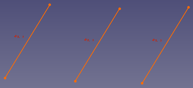
Detecting Redundant Constraints
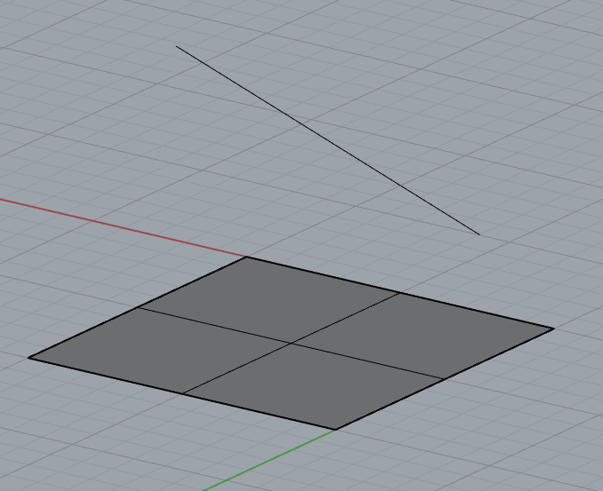
When adding constraints, redundant or conflicting constraints may occur. The following example illustrates this:
In the figure below, only two parallel constraints are needed to ensure pairwise parallelism between three line segments. Adding three parallel constraints makes one of them redundant.
When redundant or conflicting constraints exist in the GCS, the system will report the over-constrained range through GCSWConHandle::IsOverConstrained. If IsOverConstrained=true, the Handle's corresponding constraint is marked as over-constrained.
gcsSystem.
Create2dLine(handleLine1, handlePoint1, handlePoint2);
gcsSystem.
Create2dLine(handleLine2, handlePoint1, handlePoint3);
gcsSystem.
Create2dLine(handleLine3, handlePoint1, handlePoint4);
bool IsOverConstrained() const
Is the handle related to over-constrained part.
3D Constraint Solving
Constraint Element Types
Constraint element types include points, lines, and planes.
Constraint Types
Constraint types include parallel, distance, angle, and symmetry.
Distance Constraints
Distance Constraint Between Two Points
After applying a distance constraint between two points, the distance between them will be fixed to the specified value.
p1.x = 1.;
p1.y = 2.;
p1.z = 3.;
p2.x = 4.;
p2.y = 5.;
p2.z = 6.;
double dis = 2.0;
The wrapper for GCSRigidBody.
Definition AMCAXGCS.h:302
GCSWRigidBody CreateRigidBody(unsigned int id)
Create rigid body from the id.
Point3d UpdatePoint3dPosition(const GCSWRigidBody &body, const Point3d &point)
Update the point position based on the transformation of the rigid body.
Status Create3dDistPtPt(GCSWConHandle &h, const GCSWRigidBody &body1, const GCSWRigidBody &body2, const Point3d &pt1, const Point3d &pt2, double d)
Create a 3D distance point/point constraint.
Point.
Definition AMCAXGCS.h:36
Distance Constraint Between Point and Line
After applying a distance constraint between a point and a line, the distance from the point to the line will be fixed to the specified value.
p1.x = 1.;
p1.y = 2.;
p1.z = 3.;
p2.x = 4.;
p2.y = 5.;
p2.z = 6.;
p3.x = -1.;
p3.y = 1.5;
p3.z = -2.;
vec.x = p2.x - p1.x;
vec.y = p2.y - p1.y;
vec.z = p2.z - p1.z;
double dis = 2.0;
Line3d UpdateLine3dPosition(const GCSWRigidBody &body, const Line3d &line)
Update the line based on the transformation of the rigid body.
Status Create3dDistPtLn(GCSWConHandle &h, const GCSWRigidBody &body1, const GCSWRigidBody &body2, const Point3d &pt, const Line3d &ln, double d)
Create a 3D distance point/line constraint.
Line represented by a point and the normalized direction vector.
Definition AMCAXGCS.h:54
Point3d origin
A point on the line.
Definition AMCAXGCS.h:58
Vector3d direction
Normalized line direction vector.
Definition AMCAXGCS.h:62
Vector.
Definition AMCAXGCS.h:45
Distance Constraint Between Point and Plane
After applying a distance constraint between a point and a plane, the distance from the point to the plane will be fixed to the specified value.
p1.x = 1.;
p1.y = 2.;
p1.z = 3.;
p2.x = 0.;
p2.y = 0.;
p2.z = 1.;
origin.x = 0.;
origin.y = 0.;
origin.z = 0.;
normal.x = p2.x - origin.x;
normal.y = p2.y - origin.y;
normal.z = p2.z - origin.z;
double dis = 0.5;
Plane UpdatePlanePosition(const GCSWRigidBody &body, const Plane &plane)
Update the plane based on the transformation of the rigid body.
Status Create3dDistPtPl(GCSWConHandle &h, const GCSWRigidBody &body1, const GCSWRigidBody &body2, const Point3d &pt, const Plane &pl, double d)
Create a 3D distance point/plane constraint.
Plane represented by a point and the normalized normal vector.
Definition AMCAXGCS.h:68
Vector3d normal
Normalized normal vector.
Definition AMCAXGCS.h:76
Point3d origin
A point on the plane.
Definition AMCAXGCS.h:72
Distance Constraint Between Point and Torus
After applying a distance constraint between a point and a torus, the distance from the point to the torus will be fixed at the specified value.
p1.x = 0.;
p1.y = 0.;
p1.z = 0.;
p2.x = 10.;
p2.y = 10.;
p2.z = 10.;
normal.x = 0.;
normal.y = 0.;
normal.z = 1.;
double dis = 1.;
Status Create3dDistPtTorus(GCSWConHandle &h, const GCSWRigidBody &body1, const GCSWRigidBody &body2, const Point3d &pt, const Torus &tor, double d)
Create a 3D distance point/torus constraint.
Torus represented by a circular spine and the radius of circular cross-section.
Definition AMCAXGCS.h:83
Point3d center
Center of the spine curve.
Definition AMCAXGCS.h:87
double majorRadius
Radius of the spine curve.
Definition AMCAXGCS.h:95
double minorRadius
Radius of the circular cross-section.
Definition AMCAXGCS.h:99
Vector3d normal
Normal to the plane of the spline.
Definition AMCAXGCS.h:91
Distance Constraint Between Two Lines
After applying a distance constraint between two lines, they will remain parallel and the distance between them will be fixed to the specified value.
When applying distance constraints between two line segments in 3D space, there may be infinitely many solutions. To address this, we introduced the VecSense parameter to help the system filter solutions that align with the design intent.
When VecSense is set to kCodirectional, the two line segments have the same direction;
When VecSense is set to kOpposed, the two line segments have opposite directions;
When VecSense is set to kParallel, the line segments are parallel with arbitrary direction;
When VecSense is set to kReference, the effect is the same as kParallel.
p1.x = 1.;
p1.y = 2.;
p1.z = 3.;
p2.x = 4.;
p2.y = 5.;
p2.z = 6.;
p3.x = -1.;
p3.y = 1.5;
p3.z = -2.;
p3.x = 0.;
p3.y = -3.;
p3.z = 2.;
vec1.x = p2.x - p1.x;
vec1.y = p2.y - p1.y;
vec1.z = p2.z - p1.z;
vec2.x = p4.x - p3.x;
vec2.y = p4.y - p3.y;
vec2.z = p4.z - p3.z;
double dis = 2.0;
Status Create3dDistLnLn(GCSWConHandle &h, const GCSWRigidBody &body1, const GCSWRigidBody &body2, const Line3d &ln1, const Line3d &ln2, double d, VecSense vecSense)
Create a 3D distance line/line constraint. The two lines are forced to be parallel.
Distance Constraint Between Line Segment and Plane
After applying a distance constraint between a line segment and a plane, the line segment will maintain a parallel relationship with the plane, and the distance between them will be fixed at the specified value.
p1.x = 1.;
p1.y = 2.;
p1.z = 3.;
p2.x = 4.;
p2.y = 5.;
p2.z = 6.;
p3.x = 0.;
p3.y = 0.;
p3.z = 0.;
p4.x = 0.;
p4.y = 0.;
p4.z = 1.;
direction.x = p2.x - p1.x;
direction.y = p2.y - p1.y;
direction.z = p2.z - p1.z;
normal.x = p4.x - p3.x;
normal.y = p4.y - p3.y;
normal.z = p4.z - p3.z;
double dis = 0.5;
Status Create3dDistLnPl(GCSWConHandle &h, const GCSWRigidBody &body1, const GCSWRigidBody &body2, const Line3d &ln, const Plane &pl, double d)
Create a 3D distance line/plane constraint.
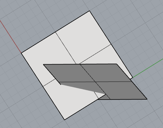
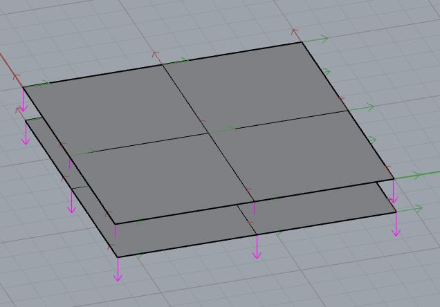
Distance Constraint Between Two Planes
After applying a distance constraint between two planes, they will maintain a parallel relationship, and the distance between them will be fixed at the specified value.
p1.x = 1.;
p1.y = 2.;
p1.z = 3.;
p2.x = 4.;
p2.y = 5.;
p2.z = 6.;
p3.x = 0.;
p3.y = 0.;
p3.z = 0.;
p4.x = 0.;
p4.y = 0.;
p4.z = 1.;
normal1.x = p2.x - p1.x;
normal1.y = p2.y - p1.y;
normal1.z = p2.z - p1.z;
normal2.x = p4.x - p3.x;
normal2.y = p4.y - p3.y;
normal2.z = p4.z - p4.z;
double dis = 0.5;
Status Create3dDistPlPl(GCSWConHandle &h, const GCSWRigidBody &body1, const GCSWRigidBody &body2, const Plane &pl1, const Plane &pl2, VecSense vecSense, double d)
Create a 3D distance plane/plane constraint.
Distance Constraint Between Plane and Torus
After applying a distance constraint between a plane and a torus, the distance between them will be fixed at the specified value.
p1.x = 10.;
p1.y = 10.;
p1.z = 10.;
p2.x = 0.;
p2.y = 0.;
p2.z = 0.;
normal1.x = 0.;
normal1.y = 0.;
normal1.z = 1.;
normal2.x = 1.;
normal2.y = 0.;
normal2.z = 0.;
double dis = 10.;
Status Create3dDistPlTorus(GCSWConHandle &h, const GCSWRigidBody &body1, const GCSWRigidBody &body2, const Plane &pl, const Torus &tor, double d)
Create a 3D distance plane/torus constraint.
Angle Constraint
When applying angle constraints between two vectors in 3D space, there may be infinitely many solutions. To address this, we introduced the VecSense parameter to help the system filter solutions that align with the design intent.
When VecSense is set to kCodirectional, the vectors satisfy:
When VecSense is set to kOpposed, the vectors satisfy:
When VecSense is set to kParallel, the vectors can be either codirectional or opposed;
When VecSense is set to kReference, the effect is the same as kParallel.
vec1.x = 1.;
vec1.y = 2.;
vec1.z = 3.;
vec2.x = -1.;
vec2.y = -3.;
vec2.z = -2.;
refvec.x = 0.;
refvec.y = 0.;
refvec.z = 1.;
Status Create3dAngVecVec(GCSWConHandle &h, const GCSWRigidBody &body1, const GCSWRigidBody &body2, const Vector3d &vector1, const Vector3d &vector2, VecSense vecSense, double a, const GCSWRigidBody &body3, const Vector3d &vector3)
Create a 3D angular constraint.
Vector3d UpdateVector3dPosition(const GCSWRigidBody &body, const Vector3d &vector)
Update the vector based on the transformation of the rigid body.
If the angle is set to AMCAX::Constants::pi, parallel constraint will be achieved. When VecSense is set to kCodirectional, the angle between the two vectors is 0°. When VecSense is set to kOpposed, the angle between the two vectors is 180°.
vec1.x = 1.;
vec1.y = 2.;
vec1.z = 3.;
vec2.x = -1.;
vec2.y = -3.;
vec2.z = -2.;
refvec.x = 0.;
refvec.y = 0.;
refvec.z = 1.;
csSystem.Solve();
constexpr double pi
Mathematical constant Pi, ratio of a circle's circumference to its diameter.
Definition Constants.hpp:42
Symmetric Constraint
Currently, it supports creating a constraint for two points to be symmetric with respect to a plane. After this constraint is applied, the distances from these two points to the plane will be equal.
p1.x = 0.;
p1.y = 1.;
p1.z = 0.;
p2.x = 0.;
p2.y = 2.;
p2.z = 1.;
origin.x = 0.;
origin.y = 0.;
origin.z = 0.;
vec.x = 1.;
vec.y = 0.;
vec.z = 0.;
Status Create3dSymmPtPt(GCSWConHandle &h, const GCSWRigidBody &body1, const GCSWRigidBody &body2, const Point3d &point1, const Point3d &point2, const Plane &plane)
Create a 3D symmetric constraint between two points about one fixed plane.
Erase
The Erase interface supports removing added objects and their associated constraints from the constraint system. It provides three overloaded forms for deleting geometric objects, rigid body objects, and constraint objects respectively.
Erase Geometric Object
Remove a geometric object from the system and automatically delete all its associated constraints.
gcsSystem.
Erase(handlePoint);
void Erase(GCSWVarGeomHandle &h)
Erase one geometry and all related constraints from the system.
Erase Rigid Body Object
Remove a rigid body object from the system and automatically delete all its associated constraints.
Erase Constraint
Remove a specified constraint object from the system.
gcsSystem.
Erase(handleHorizontal);