|
AMCAX Kernel 1.0.0.0
|
|
AMCAX Kernel 1.0.0.0
|
This tutorial provides detailed configuration methods for using mesh generation and 3D boundary layers.
By denser mesh partitioning in the fluid region near object surfaces, it better captures changes in fluid velocity profiles and the effects of viscous fluid dynamics.
Input: Selected surface mesh (triangular/quadrilateral/mixed mesh); Output: Boundary layer mesh (prism/hexahedral).
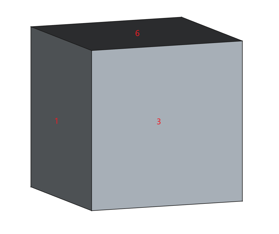
Using a simple box CAD model as an example, its face numbering is shown below. This model will be used throughout the tutorial.
Below is the most basic JSON configuration. For more complex configurations, see the Complex JSON Template.
| Class | Key | Required | Value Range | Default | Remarks |
|---|---|---|---|---|---|
| BoundaryLayer | EntityType | Yes | [Face, Edge] | — | |
| BoundaryLayer | EFPairs/SelectedEntities | Yes | — | ||
| BoundaryLayer-Basic | GrowthRate | Yes | "Constant", "Variable" [1.0,2.0] | — | Constant growth rate: "Constant" with a fixed value (uniform growth rate per layer) Variable growth rate: "Variable" with an array of values (independent growth rate per layer) |
| BoundaryLayer-Basic | InitLayerHeight | Yes | Absolute: [eps,MaxSize] Aspect: [eps,1] | — | Absolute mode: Fixed initial layer height (constant value) Aspect mode: Initial layer height = Local surface mesh length × specified factor |
| BoundaryLayer-Basic | NLayers | Yes | [1, inf] | — | |
| BoundaryLayer-Basic | ProblematicAreasTreatment | Yes | STOP, COLLAPSE, EXCLUDE | — | Problem area handling: STOP: Stops generation when parameters cannot be met COLLAPSE: Allows local collapsing of layers (may cause intersections, proximity issues, or quality degradation in boundary layers) EXCLUDE: Permits exclusion of local regions (may result in discontinuous boundary layers with intersections or quality concerns) |
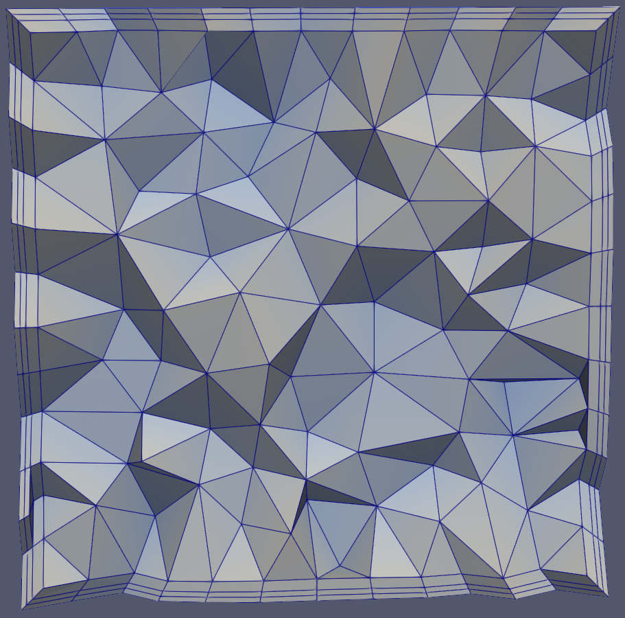
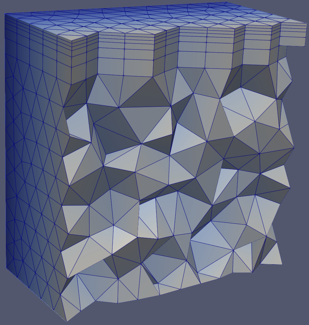
Result from this basic JSON template:
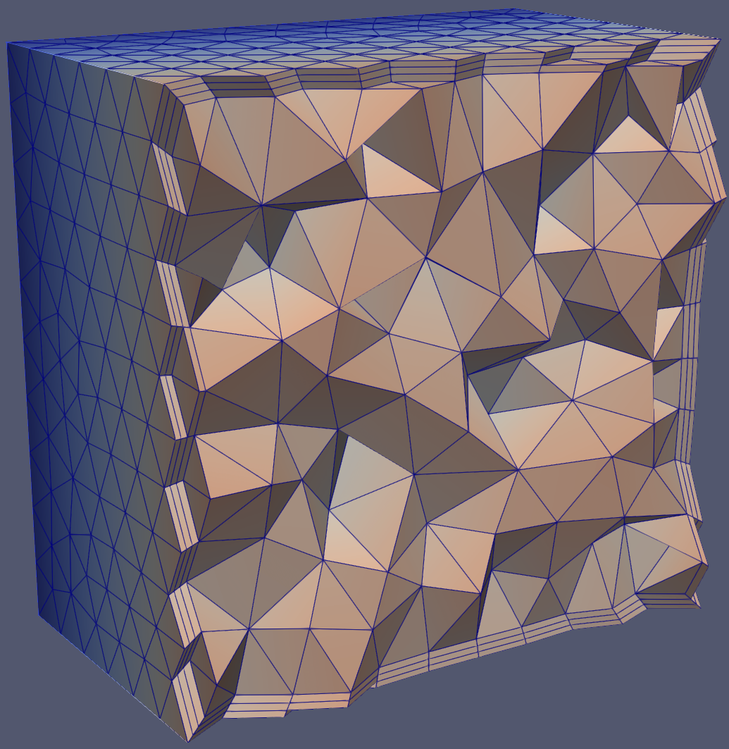
Within a solid, boundary layers grow from selected boundary faces towards the interior.
"EntityType": "Face" indicates generating 3D boundary layers from faces to solids. Specifies growth from XX face to XX solid. This example shows growth from faces (tags=1,2,3,4,5,6) to solid (tag=1). Note: Faces must be boundary edges of the solid.
Initial layer height has two modes: Absolute and Aspect. Absolute mode means each node has fixed height (compared to Aspect mode), unaffected by local surface mesh size; Aspect mode means node heights may vary, defined by multiplying local surface mesh size, with values as factors of local surface mesh length.
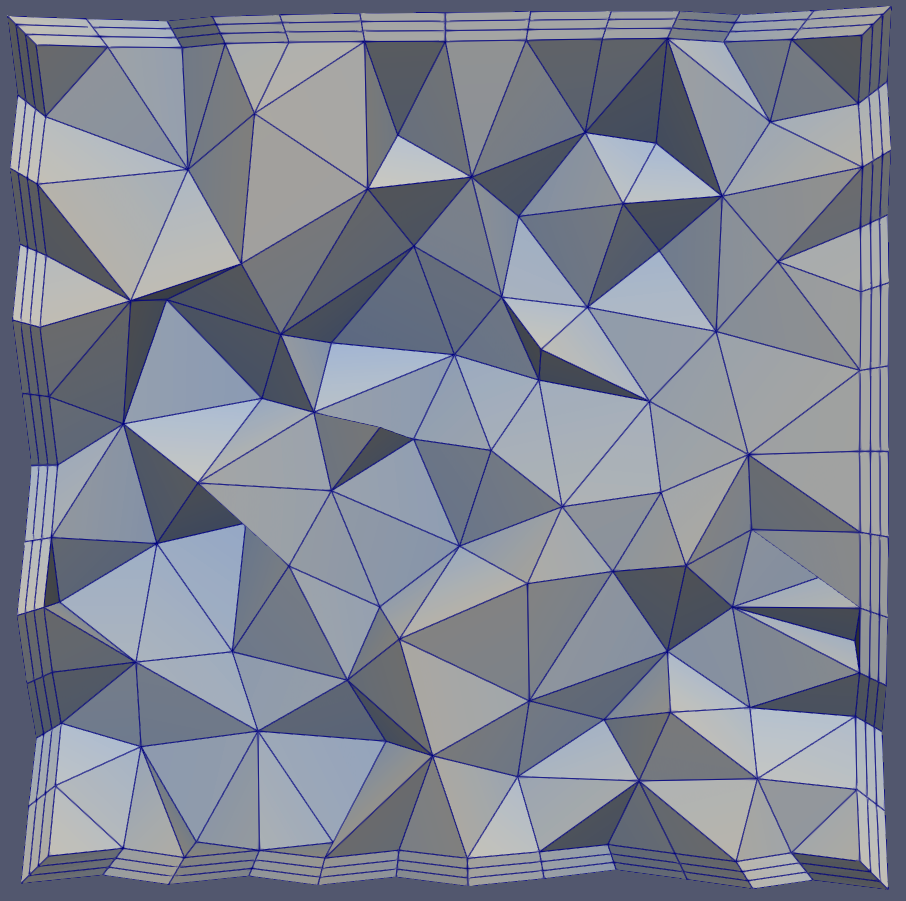
When setting initial height to Aspect mode with surface mesh size=1, first layer height becomes 1 * 0.1 = 0.1, theoretically identical to Absolute mode setting of 0.1, as shown:
Constant growth rate: Each layer grows at same rate factor (next layer vs current layer).
Variable growth rate: From second layer onward, each layer has independent growth rate (note: first layer rate is always 0, matching layer count).
NLayers: Number of boundary layers to generate.
When boundary layer generation encounters issues due to local geometric features or insufficient space for required layers, the following methods can be employed.
1.When boundary layer generation encounters issues, stop the process.
2.Collapse layers in local regions to overcome intersection, proximity, or quality issues.
3.Exclude problematic local regions to overcome intersection, proximity, or quality issues.
| Class | Key | Required | Value Range | Default | Remarks |
|---|---|---|---|---|---|
| BoundaryLayer-Basic | AdditionalOuterLayers | No | [0, inf] | 0 | Extra layers to match the last boundary layer with adjacent element size |
| BoundaryLayer-Basic | LastAspect | No | [eps, 1] | 0 | Activated when AdditionalOuterLayers is non-zero, aspect ratio of final layer |
| BoundaryLayer-Basic | FailureRetainValidLayers | No | true, false | false | Only effective when "STOP" is activated, determines whether to retain valid boundary layers upon failure |
| BoundaryLayer-Basic | MaxNumberOfConsecutiveCollapsedLayers | No | true, [1,inf] false | false | Only effective when "COLLAPSE" is activated, maximum consecutive collapsed layers |
| BoundaryLayer-SideTreatment | AutoConnectAngleLimit | No | true, false | false | Whether to auto-connect boundary layers with adjacent surface meshes |
| BoundaryLayer-SideTreatment | ConnectLimitAngle | No | [0,90] | 60 | Maximum allowed angle between boundary layer and adjacent surface mesh |
| BoundaryLayer-VectorTreatment | SmoothTopCapShellMesh | No | true, false | true | Allow vectors to deviate from original normal position; otherwise grow orthogonally |
| BoundaryLayer-VectorTreatment | SmoothVectors | No | True, [0,180] false | [true,45] | Maximum allowed angular deviation from initial position |
| BoundaryLayer-GrowthControls | MaxTopFacetEquiarealSkewness | No | true, [1,0] false | false | Maximum equiareal skewness of top triangular facets. If enabled, boundary layer growth will terminate when the maximum equiareal skewness of the top triangular facets exceeds the specified threshold. |
| BoundaryLayer-GrowthControls | MaxTopFacetWarping | No | true,[inf,0] false | false | Maximum warping value of top quadrilateral facets. If enabled, boundary layer growth will stop when the maximum warping value of top quadrilateral facets exceeds the specified threshold. |
| BoundaryLayer-GrowthControls | MaxLayerAspect | No | true,[eps,inf] false | false | Maximum aspect ratio |
| BoundaryLayer-GrowthControls | MaxAllowedAspectProceed | No | true,"LocalCollapse","ConstantHeight" false | false | When reaching max aspect ratio: ConstantHeight-maintains constant height; LocalCollapse-locally collapses layers (requires "COLLAPSE" activation) |
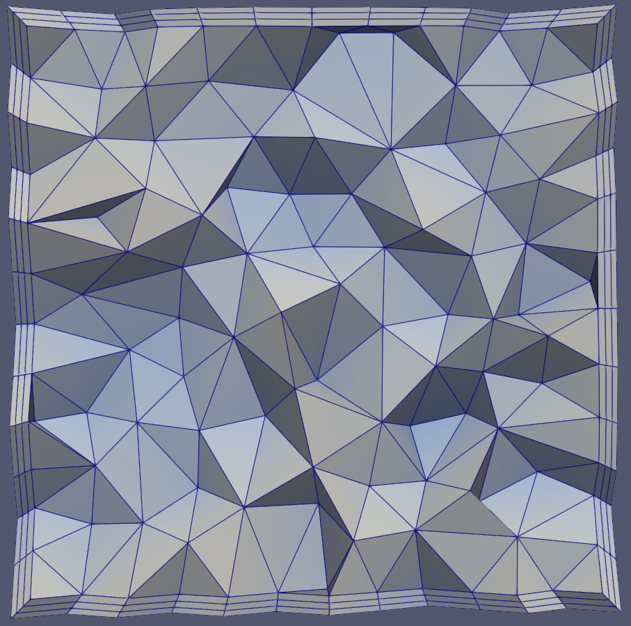
Using this complex JSON template produces results as shown below:
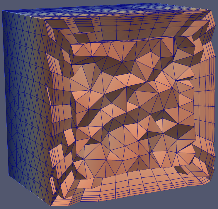
AdditionalOuterLayers: Number of extra boundary layers added to match the size of adjacent triangular elements. If the size of the last boundary layer exceeds nearby triangular elements, this parameter defaults to 0 even when set.
Aspect ratio (height/width) of the final layer. This parameter can only be set when AdditionalOuterLayers is non-zero.
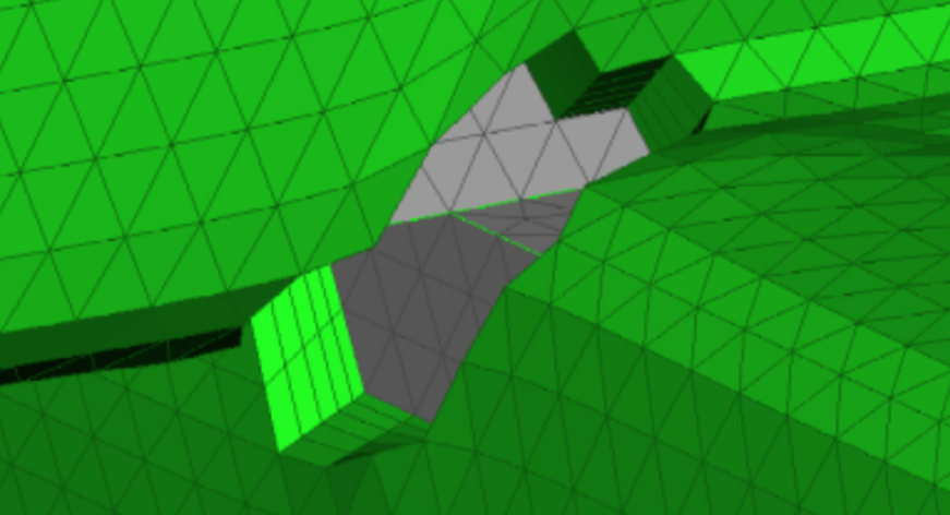
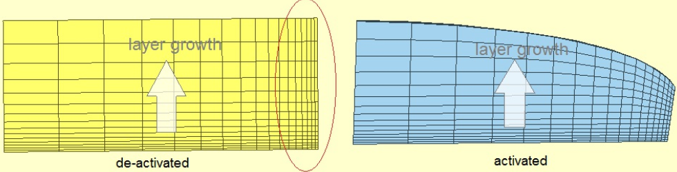
Activate this function, the boundary layer will automatically connect with adjacent surface meshes, and the surface meshes will be automatically reconstructed (the surface meshes in the area connected to the volume mesh will be consistent with the volume mesh surface in size and node position; the surface mesh types in non-connected areas will remain unchanged, and the surface meshes near the outer layer of the boundary layer will be partially reconstructed). The maximum allowable angle between the boundary layer and adjacent surface meshes needs to be specified for adjustment and connection.
As shown in the figure below, modify FSPairs to only set face 6. At this time, the connection angle between face 6 and adjacent faces 1, 2, 3, and 4 is 0 degrees. When this option is activated, the boundary layer will connect with these faces, and these faces will be automatically reconstructed.
If this function is not activated, the boundary layer will not connect with adjacent surface meshes.
For this case, if this option is not activated, it may lead to generation failure.
If this option is activated, vectors are allowed to move from their original normal position; if not activated, the layers will grow orthogonally. This operation allows the generation of more layers because the mesh "opens up" more in enclosed areas, but may result in poorer quality (less orthogonal) meshes.
If this option is activated, the user can specify the maximum allowable angle deviation from the original normal position. This operation allows the generation of more layers because the mesh "opens up" more in enclosed areas, but may result in poorer quality (less orthogonal) meshes.
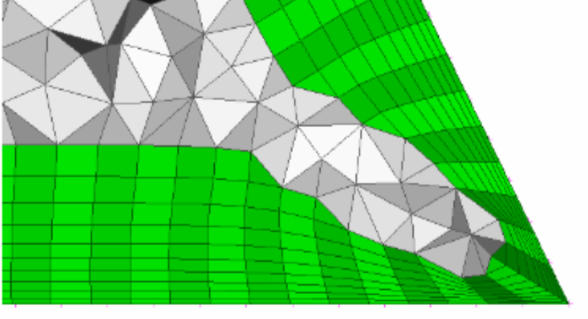
When the boundary layer grows from a non-flat starting surface, the top surface mesh may develop severely distorted elements, leading to poor quality tetrahedral generation.
If the MaxTopFacetEquiareaSkewness option is enabled, when the distortion of the top triangular surface mesh elements exceeds the set threshold, the boundary layer growth will stop. It is generally recommended to enable this option and set the threshold above 0.95.
If the MaxTopFacetWarping option is enabled, when the warping value of the top quadrilateral surface mesh elements exceeds the set threshold, the boundary layer growth will stop.
When growing boundary layers using absolute mode in areas with small surface element lengths, excessive boundary layer growth may sometimes occur, and these layers may become abnormally high. By specifying the maximum layer aspect ratio (layer element height/layer element base width), the layer height can be kept within a reasonable range.
When the boundary layer aspect ratio reaches this limit:
Click here example05 to get the full source code of the 3D boundary layer detailed JSON example. Everyone can download it as needed.