Overview
This tutorial demonstrates the basic usage of mesh generation by importing BREP or STL format files, passing mesh control parameters through JSON configuration files, and automatically generating volume meshes.
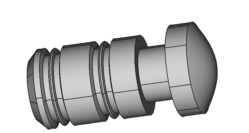
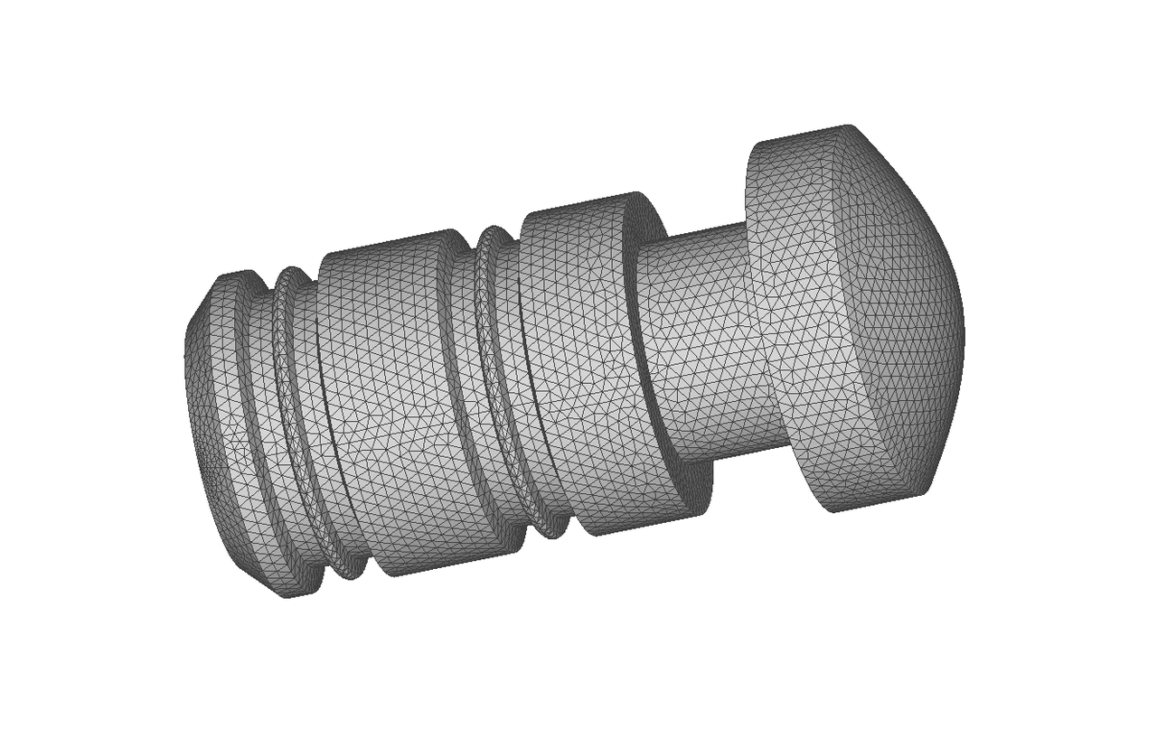
Preview of input geometry and output mesh
The left image shows the imported CAD model, while the right image displays the final generated mesh model.
The left image shows the imported STL format model, while the right image displays the final generated mesh model.
Namespaces
Namespace of all interface in the AMCAX NextMesh module.
Definition misc.docu:42
Preparation
Set the log format, provide the mesh generation control JSON file.
const std::string jsonPath = "./data/mesh_para-mesh000.json";
static AMCAX_API void InitLogger(const std::string &logFileName="", const std::string &logPattern="[%Y-%m-%dT%X%z] [%l] %v", const int64_t logFileSize=20 *1024 *1024, const int maxLogFiles=100)
set the logger. the logger is closed by default, if this function is not called
Json example
Control mesh generation by setting the following partitioning parameters: the dimension of the entity to be partitioned, MeshingDim; the maximum and minimum size of the mesh elements, MaxSize/MinSize (absolute size), which can be the bounding box diagonal length bblen of the geometric model multiplied by a certain ratio r, such as [0.01, 0.1]*bblen; the mesh growth rate, GrowthRate; the sequence of tags of the entities to be partitioned, SelectedEntities; the curvature factor, CurvatureFactor; the type of mesh elements, ElementType; the mesh partitioning method, MeshingMethod; and the number of parallel threads, ThreadNum.
{
"MeshSize": [
{
"CurvatureFactor": 0.6,
"GrowthRate": 1.0,
"MaxSize": 0.5,
"MeshingDim": 3,
"MinSize": 0.1,
"ElementType": "Tri",
"MeshingMethod": "AFTDelaunay",
"SelectedEntities": []
}
],
"ThreadNum": 1
}
Note: When importing STL files, the "MeshingMethod" currently only supports AFT. Additionally, the current size settings do not apply to input STL models.
| Class | Key | Required | Value Range | Default | Remarks |
| MeshSize | CurvatureFactor | No | [0, 1.0] | 0 | 0 means disabled; 1.0 means dividing full circle into 3 segments |
| MeshSize | GrowthRate | No | [1.0, inf] | 1.0 | |
| MeshSize | MaxSize | No | [eps, inf] | inf | Absolute size |
| MeshSize | MinSize | No | [0, inf] | 0 | Absolute size, MinSize<=MaxSize |
| MeshSize | MeshingDim | Yes | [1,2,3] | — | |
| MeshSize | SelectedEntities | Yes | Subset of entity tags under MeshingDim dimension | — | Empty value means all entities in specified dimension |
| MeshSize | ElementType | No | [Tri, Quad, Mixed, RTri] | Tri | Only valid when MeshingDim=2; Tri-triangle; Quad-quadrilateral; RTri-right triangle; Mixed-hybrid triangle/quadrilateral mesh |
| MeshSize | MeshingMethod | No | [Transfinite, Delaunay, AFTDelaunay, AFT] | AFTDelaunay (when ElementType="Tri") | Only valid when MeshingDim=2; Transfinite-generates structured grids (for 2/3/4-edged faces); Delaunay method for triangle generation; AFTDelaunay: a combined advancing-front and Delaunay method for triangle generation. |
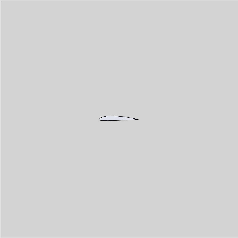
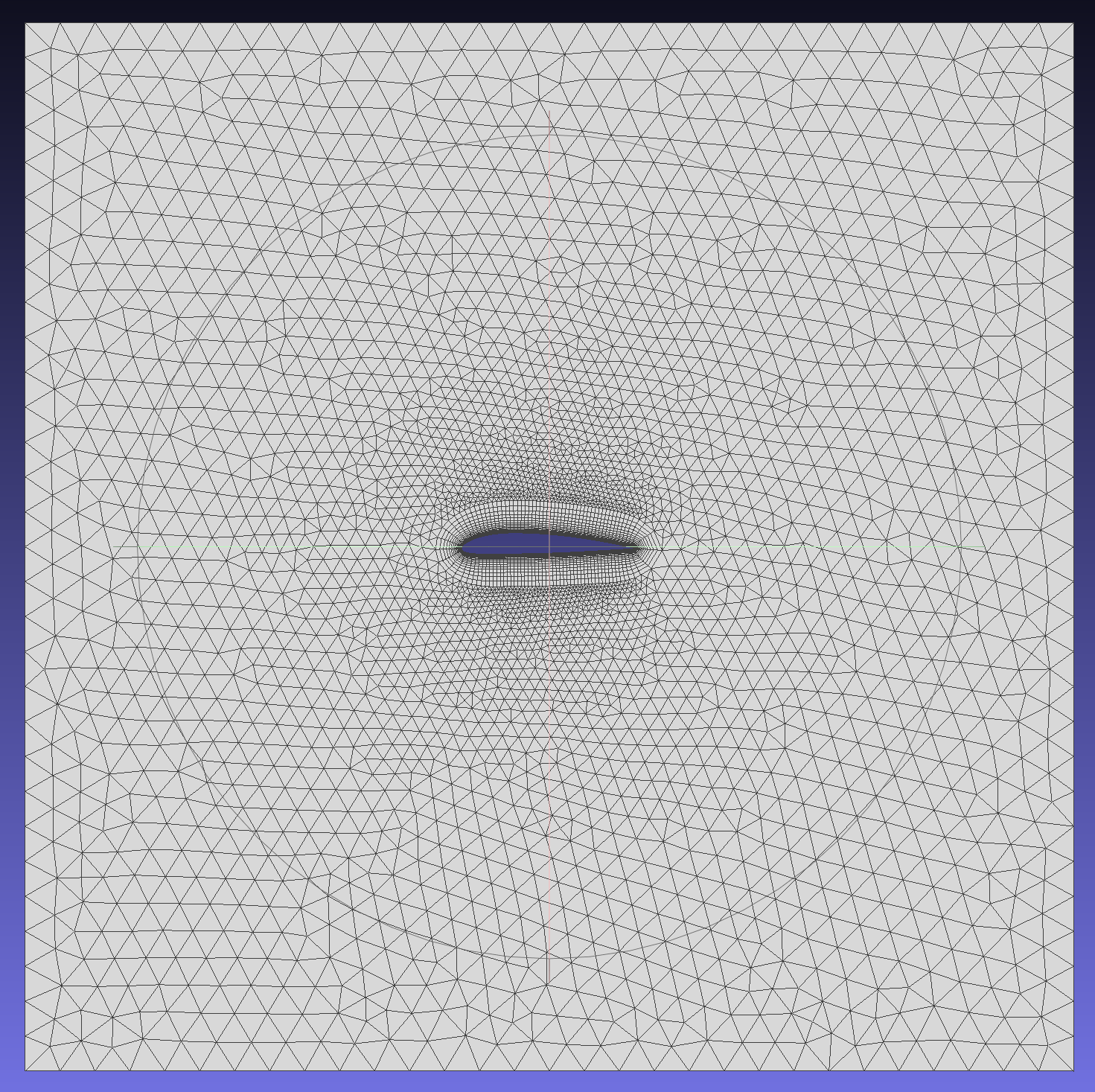
JSON example - Planar boundary layer
This example generates a planar boundary layer hybrid mesh for a two-dimensional airfoil.
{
"BoundaryLayer": [
{
"DistributionType": "Separation",
"EntityType": "Edge",
"EFPairs": [
{
"E": 5,
"F": 1
},
{
"E": 6,
"F": 1
}
],
"Basic": {
"GrowthRate": {
"Constant": 1.2
},
"InitLayerHeight": {
"Absolute": 0.01
},
"NLayers": 20,
"ProblematicAreasTreatment": "STOP"
}
}
],
"MeshSize": [
{
"CurvatureFactor": 0.2,
"GrowthRate": 1.1,
"MaxSize": 0.2,
"MeshingDim": 1,
"MinSize": 0.1,
"SelectedEntities": [ 5, 6 ]
},
{
"CurvatureFactor": 0.2,
"GrowthRate": 1.0,
"MaxSize": 2,
"MeshingDim": 2,
"MinSize": 1,
"SelectedEntities": []
}
],
"ThreadNum": 1
}
The following are the imported CAD model and the final generated mesh model.
For more complex configurations, please refer to 2D Boundary Layer Detailed JSON Example
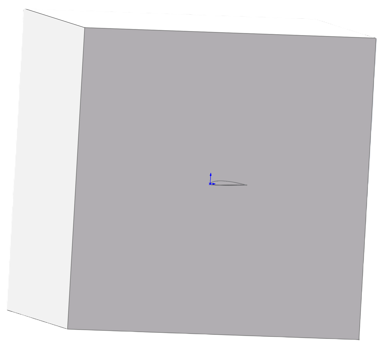
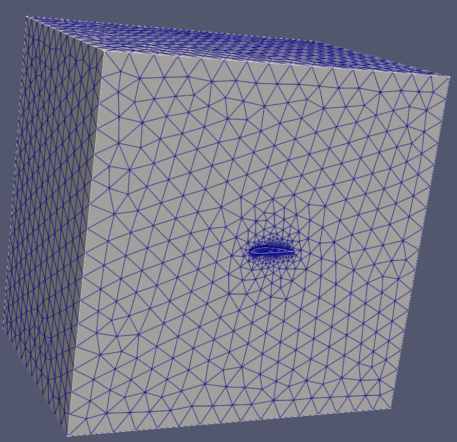
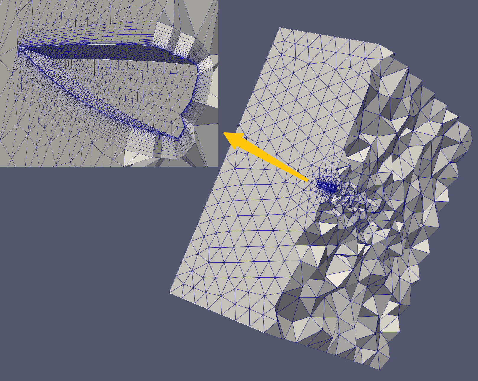
JSON Example - Spatial boundary layer
This example generates a spatial boundary layer hybrid mesh for a three-dimensional airfoil.
{
"Distribution": [],
"BoundaryLayer": [
{
"DistributionType": "Separation",
"EntityType": "Face",
"FSPairs":
[
{
"F": 1,
"S": 1
},
{
"F": 8,
"S": 1
},
{
"F": 9,
"S": 1
}
],
"Basic":
{
"GrowthRate":
{
"Constant": 1.2
},
"InitLayerHeight":
{
"Absolute": 0.002
},
"NLayers": 20,
"ProblematicAreasTreatment": "STOP"
},
"SideTreatment":
{
"AutoConnectAngleLimit":true,
"ConnectLimitAngle": 60
}
}
],
"MeshSize": [
{
"CurvatureFactor": 0.2,
"GrowthRate": 1.3,
"MaxSize": 0.2,
"MeshingDim": 1,
"MinSize": 0.1,
"SelectedEntities": [ 1, 2, 3, 4, 17, 18 ]
},
{
"CurvatureFactor": 0.2,
"GrowthRate": 1.1,
"MaxSize": 5,
"MeshingDim": 2,
"MinSize": 1,
"SelectedEntities": [ 2, 3, 4, 5, 6, 7 ]
},
{
"CurvatureFactor": 0.2,
"GrowthRate": 1.1,
"MaxSize": 5,
"MeshingDim": 2,
"MinSize": 0.1,
"SelectedEntities": [ 1, 8, 9 ]
},
{
"CurvatureFactor": 0.2,
"GrowthRate": 1.1,
"MaxSize": 5,
"MeshingDim": 3,
"MinSize": 1,
"SelectedEntities": []
}
],
"ThreadNum": 1
}
The following are the imported CAD model and the final generated mesh model, along with the section view.
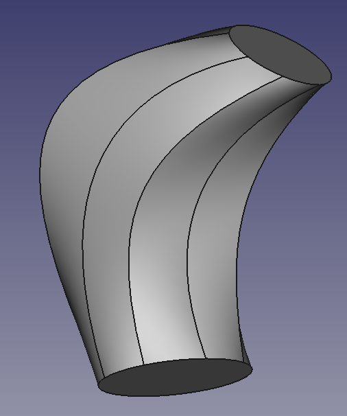
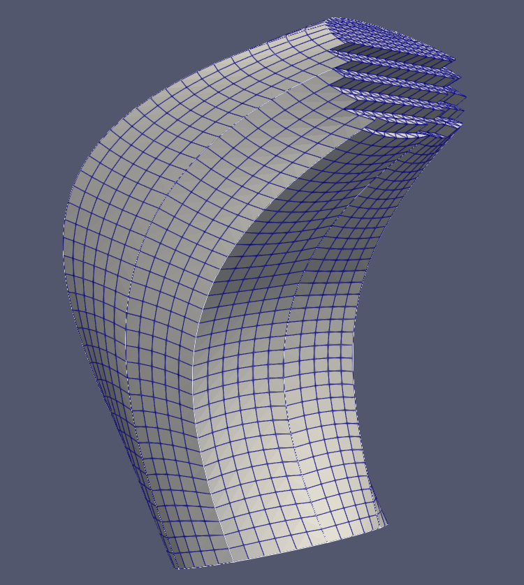
JSON example - Sweep mesh
Sweep meshing only supports a single sweep body, the source surface may consist of multiple faces, while the target surface can only include a single face. The side faces must be either 2-sided, 3-sided, or 4-sided faces.
{
"Sweep": [
{
"EntityType": "Face",
"Domain": 1,
"Source": [9],
"Target": [10]
}
],
"MeshSize": [
{
"CurvatureFactor": 0.2,
"GrowthRate": 1.0,
"MaxSize": 1,
"MeshingDim": 3,
"MinSize": 0.1,
"SelectedEntities": []
}
],
"ThreadNum": 1
}
The following are the imported CAD model and the generated mesh model.
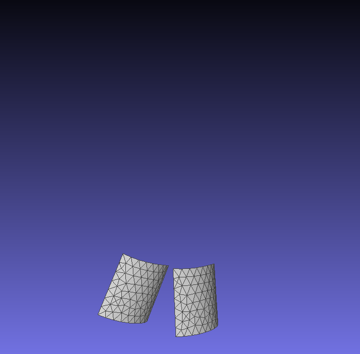
JSON Example - Copy mesh
The mesh of one or multiple entities (edges or faces) can be copied onto a single target entity. This is applicable in scenarios where the mesh topology of the source and target must be completely consistent, such as in periodic meshes.Important Notes:The source can include multiple entities, but the target must consist of only a single entity;The topological structure of the source and target must be entirely consistent;When copying face meshes, if the source face and target face have consistent topology, it is not necessary to specify the boundary correspondence "EdgeCorrespondence";If multiple boundary edges correspond to a single boundary edge, the correspondence of the boundary edges must be correctly specified.
{
"Copy": [
{
"EntityType": "Face",
"Source": [ 43 ],
"Target": [ 47 ]
}
],
"MeshSize": [
{
"CurvatureFactor": 0,
"GrowthRate": 1.0,
"MaxSize": 3,
"MeshingDim": 2,
"MinSize": 1,
"SelectedEntities": [ 43, 47 ]
}
],
"ThreadNum": 1
}
Using "Entity" as a face, the following are the imported CAD model and the copied mesh.
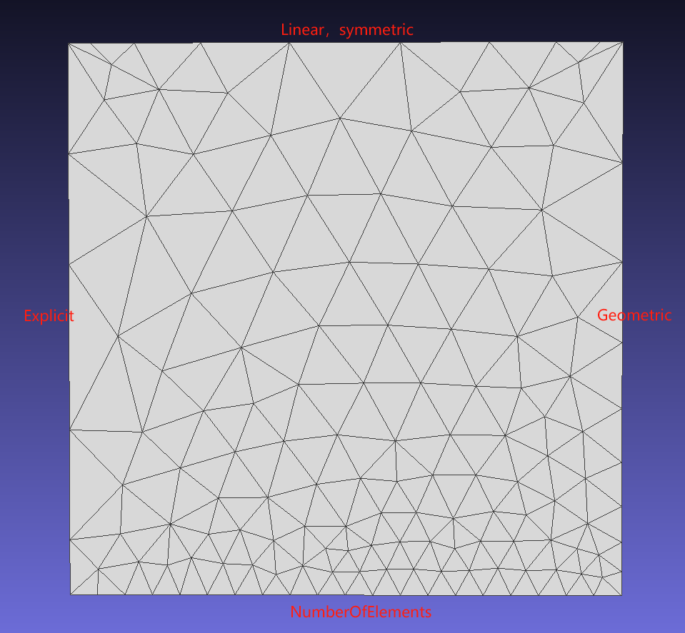
JSON Example - Multiple line mesh generation methods
Method 1: Specify the number of elements on an edge;
Method 2: Explicitly specify the length ratio of each segment of elements on the edge;
Method 3: Partition based on a pre-defined function (Linear/Geometric);
{
"Distribution": [
{
"EntityType": "Edge",
"SelectedEntities": [ 1 ],
"DistributionType": "NumberOfElements",
"NElement": 20
},
{
"EntityType": "Edge",
"SelectedEntities": [ 2 ],
"DistributionType": "Explicit",
"Orientation": "Forward",
"DistributionPara": [ 0.1, 0.3, 0.6, 0.8 ]
},
{
"EntityType": "Edge",
"SelectedEntities": [ 3 ],
"DistributionType": "Linear",
"Orientation": "Forward",
"Symmetric": true,
"NElement": 9,
"EndBeginElementRatio": 5
},
{
"EntityType": "Edge",
"SelectedEntities": [ 4 ],
"DistributionType": "Geometric",
"Orientation": "Forward",
"Symmetric": false,
"NElement": 9,
"EndBeginElementRatio": 5
}
],
"MeshSize": [
{
"CurvatureFactor": 1,
"GrowthRate": 1.0,
"MaxSize": 5,
"MeshingDim": 2,
"MinSize": 0.1,
"SelectedEntities": [1]
}
],
"ThreadNum": 1
}
| Class | Key | Required | Value Range | Default Value | Notes |
| Distribution | EntityType | Yes | Edge | – | |
| Distribution | SelectedEntities | Yes | Can be empty | – | Edge tags |
| Distribution | DistributionType | Yes | NumberOfElements, Explicit, Linear, Geometric | – | Distribution type |
| Distribution | Orientation | No | Forward, Reverse | Forward | Orientation |
| Distribution | Symmetric | No | true, false | false | Symmetric distribution |
| Distribution | NElement | Yes | >=1 | – | Number of segments |
| Distribution | EndBeginElementRatio | Yes | >0 | – | Ratio of the length of the last segment to the first segment |
| Distribution | DistributionPara | Yes | (0.0, 1.0) | – | Strictly increasing sequence |
The following are the results of various line mesh mesh generation methods.
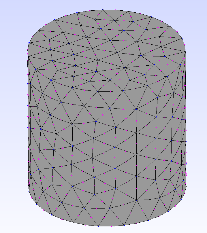
JSON Example - High-Order Mesh
Supports the generation of second-order high-order meshes and exports files in VTK or Gmsh format.
{
"MeshSize": [
{
"CurvatureFactor": 0.2,
"GrowthRate": 1.0,
"MaxSize": 5.0,
"MeshingDim": 3,
"MinSize": 2.0,
"SelectedEntities": []
}
],
"ElementOrder": {
"Order": 2,
"OnGeom":true,
"Serendipity":true
},
"ThreadNum": 1
}
| Class | key | Required | Value Range | Default Value | Remarks |
| ElementOrder | Order | Yes | [1,2] | – | |
| ElementOrder | OnGeom | No | [true,false] | true | Whether to conform to the geometry |
| ElementOrder | Serendipity | No | [true,false] | true | true, high-order points only exist on edges |
Below is an example of a high-order mesh.
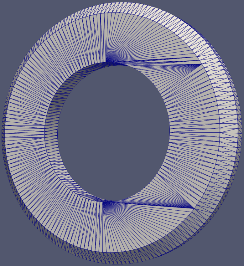
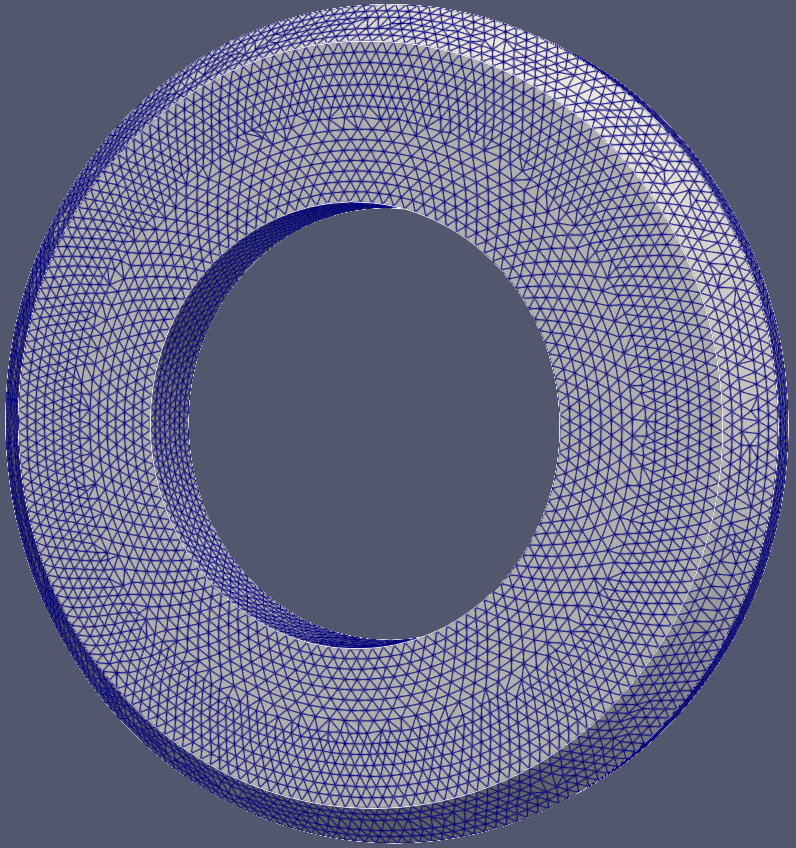
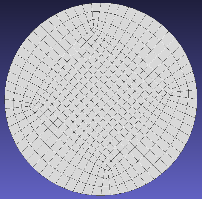
JSON Example - Template Mesh
| Class | Key | Required | Value Range | Default Value |
| Pattern | Type | Yes | ["Circle"] | —— |
| Pattern | Mode | Yes | ["OGrid"] | —— |
| Pattern | Zones | Yes | ≥ 1, integer | —— |
Circular-like Face
Mode: OGrid
{
"Pattern": [
{
"MeshingDim": 2,
"SelectedEntities": [ 1 ],
"Type": "Circle",
"Mode": "OGrid",
"Zones": 3
}
],
"Distribution": [
{
"EntityType": "Edge",
"SelectedEntities": [ 1 ],
"DistributionType": "NumberOfElements",
"NElement": 64
}
],
"MeshSize": [
{
"CurvatureFactor": 0.2,
"GrowthRate": 1.0,
"MaxSize": 2,
"ElementType": "Quad",
"MeshingDim": 2,
"MinSize": 1,
"SelectedEntities": [ 1 ]
}
]
}
The following is the template mesh.
Import Model
Import BREP file.
std::vector<NMShape>shapes = { shape };
Class of model in NextMesh.
Definition NMAPIModel.hpp:22
AMCAX_API void ImportModel(const std::vector< NMShape > &shapes, const bool replace=true)
Load a cad model represented by AMCAX TopoShape. Note: this import method does not specify any entity...
Base class of shape, containing an underlying shape with a location and an orientation.
Definition TopoShape.hpp:15
Import STL file.
const std::string cadstr = "./data/escapement.stl";
AMCAX_API void ImportSTL(const std::string &filePath, const double dihedralAngle, const double curveAngle, const double mergeSmallPatchRatio=0.0, const double tolerance=0.0)
Load a stl model.
constexpr double pi
Mathematical constant Pi, ratio of a circle's circumference to its diameter.
Definition Constants.hpp:42
Parameter descriptions:
| Option | Value Range | Description |
| dihedralAngle | [0, Constants::pi] | When the dihedral angle between two adjacent triangular facets of an edge exceeds this value, the edge will be identified as a feature edge |
| curveAngle | [0, Constants::pi] | For connected feature edges, if the angle between two adjacent discrete edges exceeds this threshold, the feature edge will be split into two sub-edges at their shared vertex |
| mergeSmallPatchRatio | [0, 1] | Given total feature edge length l, any Face boundary with perimeter less than this ratio×l will be merged with adjacent patches |
| tolerance | [0, inf] | Vertices will be merged if their coordinate differences in all axes are below this threshold |
Generate/get mesh
generate mesh by importing mesh generation control parameter via JSON file.
nlohmann::json paraJ = nlohmann::json::parse(std::ifstream(jsonPath));
AMCAX_API void GenerateMesh(const std::string &configJson)
Generates the mesh for the current model based on provided configuration parameters.
AMCAX_API NMMesh GetMesh()
Get the mesh handle. Note one model only holds a unique mesh.
Get mesh and geometry information
Get the model's entity list, the BRep (boundary representation) relationships of entities, and their boundingboxes. For each entity, obtain the types of meshes it contains, the mesh elements, vertices, and the global IDs of the mesh elements and vertices, along with other related information.
for (
DimType dim : {DimType::D0, DimType::D1, DimType::D2, DimType::D3})
{
std::vector<NMEntity> etVec;
for (auto ent : etVec)
{
std::vector<NMEntity> parentVec;
std::vector<NMEntity> childVec;
std::vector<Orientation> ories;
auto entElemNum = meshapi.EntityGetElementCount(ent);
for (size_t i = 0; i < entElemNum; i++)
{
auto elem = meshapi.EntityGetElementByIndex(ent, i);
}
auto entNodeNum = meshapi.EntityGetNodeCount(ent);
for (size_t i = 0; i < entNodeNum; i++)
{
auto node = meshapi.EntityGetNodeByIndex(ent, i);
}
}
}
auto elemTotalNum = meshapi.GetElementCount();
for (size_t i = 0; i < elemTotalNum; i++)
{
auto elem = meshapi.GetElementByIndex(i);
auto elemId = meshapi.ElementGetID(elem);
auto elemType = meshapi.ElementGetType(elem);
auto nodeCount = meshapi.ElementGetNodeCount(elem);
for (size_t in = 0; in < nodeCount; in++)
{
auto node = meshapi.ElementGetNode(elem, in);
auto nodeId = meshapi.NodeGetID(node);
auto nodeEnt = meshapi.NodeGetEntity(node);
auto nodePos = meshapi.NodeGetPosition(node);
double u = meshapi.NodeGetFirstParameter(node);
double v = meshapi.NodeGetSecondParameter(node);
}
}
auto nodeTotalNum = meshapi.GetNodeCount();
for (size_t i = 0; i < nodeTotalNum; i++)
{
auto node = meshapi.GetNodeByIndex(i);
}
AMCAX_API void GetEntities(std::vector< NMEntity > &ents, const DimType dim)
get all the entities in the specified dim
AMCAX_API EntTag EntityGetTag(const NMEntity &ent)
get the tag of the given entity
AMCAX_API DimType EntityGetDim(const NMEntity &ent)
get the dimension of the given entity
AMCAX_API void GetChildAdjacentEntities(std::vector< NMEntity > &children, std::vector< Orientation > &oris, const NMEntity &ent)
get all the entities in dim-1 contained by the entity
AMCAX_API void GetParentAdjacentEntities(std::vector< NMEntity > &parents, const NMEntity &ent)
get all the entities in dim+1 that contain the entity
AMCAX_API void GetBBox(NMPoint3 &pmin, NMPoint3 &pmax, const NMEntity &ent=nullptr)
get the boundingbox of the entity. when ent = nullptr, return the model bbox
AMCAX::Coord3d NMPoint3
Type of point/vector.
Definition Macros.hpp:25
DimType
Type of dimension.
Definition Macros.hpp:71
Mesh Refinement
Supports conformal/non-conformal refinement for triangle/quad/tetrahedral mesh types.
Mesh Quality Computation
Outputs mesh element quality metrics for specified commercial software, including aspect ratio, skewness, maximum/minimum angles, etc.
double quality = meshapi.ComputeQuality(elem, QualityType::SkewnessByVolume, CommercialSoftware::Fluent);
Set the face groups
Add, delete, modify, and query of the face groups.
std::vector<EntTag> entTags;
std::set<std::string> pNames;
AMCAX_API void GetEntitiesInPhysicalSet(std::vector< EntTag > &entTags, const DimType dim, const std::string &pName)
get entities in the specified physical set
AMCAX_API void GetPhysicalSets(std::set< std::string > &pNames, const DimType dim)
get all the physical sets in the specified dim
AMCAX_API void CreatePhysicalSet(const DimType dim, const std::vector< EntTag > &entTags, const std::string &pName)
create a new physical set for the specified entities with specified dimension
Output mesh files
Output mesh files in user-specified formats, such as OBJ/VTK/Fluent MSH/Gmsh MSH.
meshapi.Write("result.vtk", OutFileType::VTK);
meshapi.Write("result.obj", OutFileType::OBJ);
meshapi.Write("result.msh", OutFileType::FLUENT_MSH);
meshapi.WriteGmsh4("result.msh", false, true);
Click here example01 to get the full source code of the mesh partitioning example. Everyone can download it as needed.
Appendix
The complete code for this example is listed below:
#include <fstream>
#include <nlohmann/json.hpp>
#include <set>
void GenMesh()
{
const std::string jsonPath = "./data/mesh_para-mesh000.json";
std::vector<NMShape>shapes = { shape };
nlohmann::json paraJ = nlohmann::json::parse(std::ifstream(jsonPath));
for (
DimType dim : {DimType::D0, DimType::D1, DimType::D2, DimType::D3})
{
std::vector<NMEntity> etVec;
for (auto ent : etVec)
{
std::vector<NMEntity> parentVec;
std::vector<NMEntity> childVec;
std::vector<Orientation> ories;
auto entElemNum = meshapi.EntityGetElementCount(ent);
for (size_t i = 0; i < entElemNum; i++)
{
auto elem = meshapi.EntityGetElementByIndex(ent, i);
}
auto entNodeNum = meshapi.EntityGetNodeCount(ent);
for (size_t i = 0; i < entNodeNum; i++)
{
auto node = meshapi.EntityGetNodeByIndex(ent, i);
}
}
}
auto elemTotalNum = meshapi.GetElementCount();
for (size_t i = 0; i < elemTotalNum; i++)
{
auto elem = meshapi.GetElementByIndex(i);
auto elemId = meshapi.ElementGetID(elem);
auto elemType = meshapi.ElementGetType(elem);
auto nodeCount = meshapi.ElementGetNodeCount(elem);
for (size_t in = 0; in < nodeCount; in++)
{
auto node = meshapi.ElementGetNode(elem, in);
auto nodeId = meshapi.NodeGetID(node);
auto nodeEnt = meshapi.NodeGetEntity(node);
auto nodePos = meshapi.NodeGetPosition(node);
double u = meshapi.NodeGetFirstParameter(node);
double v = meshapi.NodeGetSecondParameter(node);
}
}
auto nodeTotalNum = meshapi.GetNodeCount();
for (size_t i = 0; i < nodeTotalNum; i++)
{
auto node = meshapi.GetNodeByIndex(i);
}
std::vector<EntTag> entTags;
std::set<std::string> pNames;
meshapi.Write("result.vtk", OutFileType::VTK);
meshapi.Write("result.obj", OutFileType::OBJ);
meshapi.Write("result.msh", OutFileType::FLUENT_MSH);
meshapi.WriteGmsh4("result.msh", false, true);
}
int main()
{
GenMesh();
}