AMCAX Kernel
Geometry kernel for CAD/CAE/CAM
|
AMCAX Kernel 1.0.0.0
|
|
AMCAX Kernel 1.0.0.0
|
Boundary Representation (BRep) is currently the most popular data structure. BRep can maintain completeness and unambiguity while reducing storage requirements. BRep uses points, curves, and surfaces on the boundaries of entities to represent those entities, and the volume information of the entity is derived from the three-dimensional space enclosed within the boundary. Its two basic elements are: geometric information (Point, Curve, Surface); and topological information (Vertex, Edge, Face connectivity).
Let’s first define the various levels of topological structures in a BRep:
Here are some examples to help you better understand the concept.
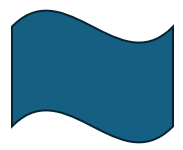
It’s easy to see that this example consists of 4 Vertices, 4 Edges, 1 Wire, and 1 Face.
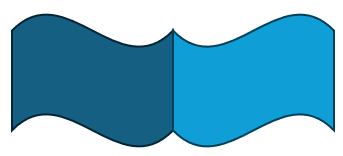
Since the overlapping vertices and edges in the middle are shared, this example consists of 6 Vertices, 7 Edges, 2 Wires, 2 Faces, and 1 Shell.
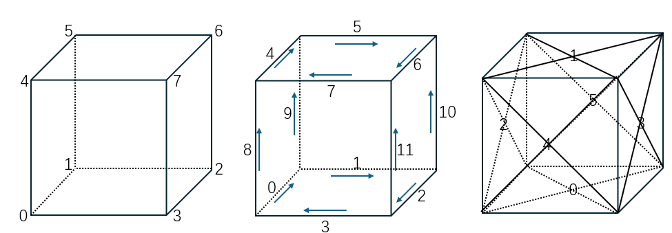
This example consists of 8 Vertices, 12 Edges, 6 Wires, 6 Faces, and 1 Shell.
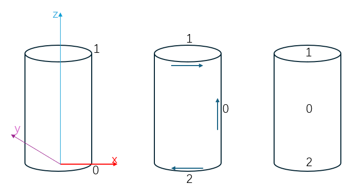
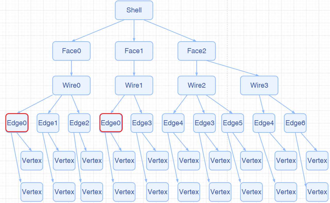
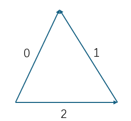
This example consists of 2 Vertices, 3 Edges, 3 Wires, 3 Faces, and 1 Shell. Edge 0 is reused in the Wire, making it a classic Seam Edge.
 |  |
This example consists of 2 Vertices, 3 Edges, 1 Wire, 1 Face, and 1 Shell. In this case, there is not only a Seam Edge but also two Edges with no length. Despite having no length in 3D, these two Edges do have length in the parametric domain, making them classic Degenerated Edges.
Next, we will introduce some common types of Edges.
In a closed TopoShape (like a Shell or Solid), the most common Edge is an edge that is adjacent to two different Faces. An ordinary Edge belongs to two different Faces and has a non-zero length.
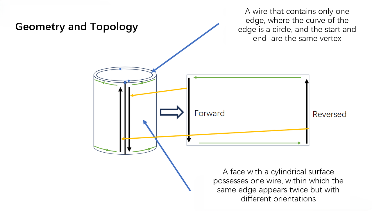
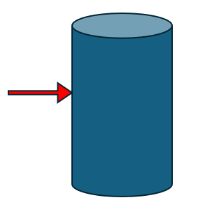
A common special case is the side edge of a cylinder. This Edge is owned by one Face and appears twice in the same Wire of that Face (once forward, once backward). Seam Edges are valid.
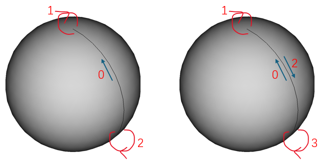
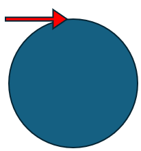
A common special case is the top edge of a sphere. This Edge has zero length and degenerates into a point. Degenerated Edges are valid.
An Edge that belongs to only one Face and appears only once in that Face’s Wire is called a Free Edge. Free Edges are invalid in a closed TopoShape.
An Edge that belongs to more than two Faces in one Shape or Solid is called a Non-Manifold Edge. Non-Manifold Edges are invalid.
Let’s first introduce the tree structure of a TopoShape, as shown below:
Traversing a topological structure is a common operation. Our kernel provides two ways: AMCAX::TopoExplorer and AMCAX::WireExplorer. Let’s introduce both methods one by one.
AMCAX::TopoExplorer can traverse through specified types (Shape, Compound, CompSolid, Solid, Shell, Face, Wire, Edge, Vertex) within a TopoShape in a preorder manner, based on its tree structure, to find child shapes of the specified type. For example, to traverse the Faces of a TopoShape, you can use the following code:
It’s important to note that AMCAX::TopoExplorer does not consider duplicates (level of "equality"). That is, if an Edge is shared by two Faces, AMCAX::TopoExplorer will traverse this Edge twice. If you don’t want to traverse it twice, you can use a std::unordered_set to remove duplicates, like this:
In the above, we discussed duplication, which inherently implies the definition of "equality". Next, we will introduce the three levels of "equality" for TopoShape, with increasing strictness:
It's not difficult to realize that when we need to traverse the edges of a Wire in order, AMCAX::TopoExplorer cannot actually meet the demand. However, AMCAX::WireExplorer can fulfill this requirement, though the traversal speed will decrease.
Due to the tree structure and pre-order traversal, each Edge (similarly for Vertex, Wire, and Face) actually has its own index. The AMCAX::TopoExplorerTool class provides some convenient traversal operations. AMCAX::TopoExplorerTool::MapShapes can get an ordered set of indices for a specific type of topological structure (such as Edge), and the resulting set is unique.
In fact, this index matches the one shown in the lower-left corner of FreeCAD (FreeCAD starts from 1, while our kernel starts from 0).
AMCAX::TopoExplorerTool::MapShapesAndAncestors can retrieve a map from child shapes to their corresponding parent shapes, while AMCAX::TopoExplorerTool::MapShapesAndUniqueAncestors also provides a map. The difference is that when a seam edge is input, MapShapesAndUniqueAncestors will return a single associated face, while MapShapesAndAncestors will return two associated faces. For example, the mapping from Edge to its associated Face can be obtained as follows:
Determining whether an Edge is degenerated is very important. For example, we should not sample along a degenerated edge. We can use AMCAX::TopoTool::Degenerated to check.
You can determine whether an Edge is a seam edge using AMCAX::TopoTool::IsClosed.
A Vertex contains only one Point, representing a point in 3D space. The method to access the Point from a Vertex is AMCAX::TopoTool::Point :
curve3d is a 3D parametric curve. pcurve is a 2D parametric curve. pcurve is bound to <Edge, Surface, Location>, meaning Edge, Surface, and Location are the indexes of a pcurve.
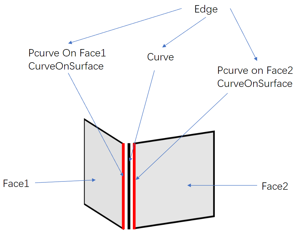
An Edge typically has one curve3d and two pcurves. In fact, a 3D parametric curve can also be constructed using a pcurve and surface, but due to tolerance, the two resulting 3D parametric curves will not coincide with the curve3d. In geometric modeling, there is no requirement for the number of curves in an Edge; it is fine if there are no curves. However, unless in special cases, the final geometric model should include one curve3d and two pcurves.
Next, let's introduce some special cases:
If the Edge lies on a plane (Geom3Plane), no additional pcurve is needed, because the Edge on the plane can be directly represented by a curve3d.
A Seam Edge has one curve3d and two pcurves, both on one Face. The difference between the two pcurves lies in the Orientation of the Edge: one pcurve corresponds to the forward direction of the Edge, and the other corresponds to the reverse direction.
A Degenerated Edge has only one pcurve, with no curve3d.
A Free Edge has one curve3d and one pcurve.
It is important to note that the kernel does not provide functionality for calculating a pcurve from a curve3d. The correct modeling approach is to first construct the pcurve and then use the pcurve and surface to calculate the curve3d:
The method to access the Curve3d of an Edge is AMCAX::TopoTool::Curve :
There are a few points to note:
1.The interface returns the raw curve. If an Edge is a segment formed by a Geom3Line and two Vertices, this interface will return an infinitely long line (Geom3Line), with fp and lp being the parameters of the two Vertices on the curve.
2.AMCAX::TopoTool::Curve has an overloaded function, one that takes a loc input and one that does not. The interface with loc returns a pointer to the curve memory inside the edge, while the interface without loc, when the edge's location is null, returns a pointer to the memory; otherwise, it returns a pointer to a newly constructed curve.
3.If the input is a degenerated edge, a null pointer will be returned.
4.The interface with loc returns a Curve with an additional location compared to the actual location, and applying location.Transformation() directly on the Curve is prohibited, as this will alter the edge's content. The correct approach is to copy the Curve and then apply transformations to the CopyCurve:
The method to access the pcurve is AMCAX::TopoTool::CurveOnSurface :
It is important to note that if the input is a seam edge, special handling is required. Depending on the Edge's Orientation, different pcurves will be returned:
In the above example, two pcurves for the seam edge of a cylinder were obtained. The orientation of these two pcurves is always consistent and matches the orientation of the curve3d. The edge's orientation is not considered.
A Face contains only one Surface. The method to access the Surface is AMCAX::TopoTool::Surface:
The interface with loc returns a Surface with an additional location compared to the actual location, and applying location.Transformation() directly on the Surface is prohibited, as this will alter the face's content. The correct approach is to copy the Surface and then apply transformations to the CopySurface:
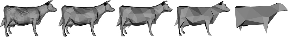
Mesh refers to a triangular mesh. The significance of Mesh in CAD is for rendering. Since the basic drawing elements in OpenGL are points, line segments, and triangles, curves must be discretized into polygons for rendering, and surfaces must be discretized into Mesh for rendering. Therefore, in applications with a graphical user interface (GUI), the BRep model that is seen is typically visualized through a triangular mesh. As shown in the figure below.
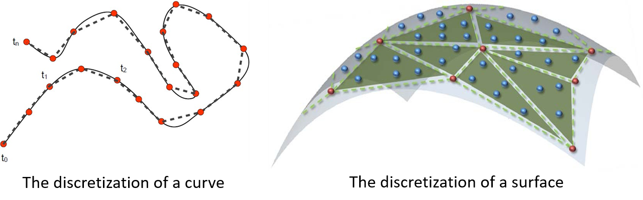
Clearly, discretization introduces errors, meaning that the BRep model displayed in applications with a GUI is not the model itself, but rather its Mesh. The error between the two is determined by the discretization precision, which is the density of the mesh. Considering that Mesh generation in CAD models must be very fast, the precision of the Mesh is understandably not very high.
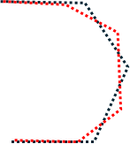
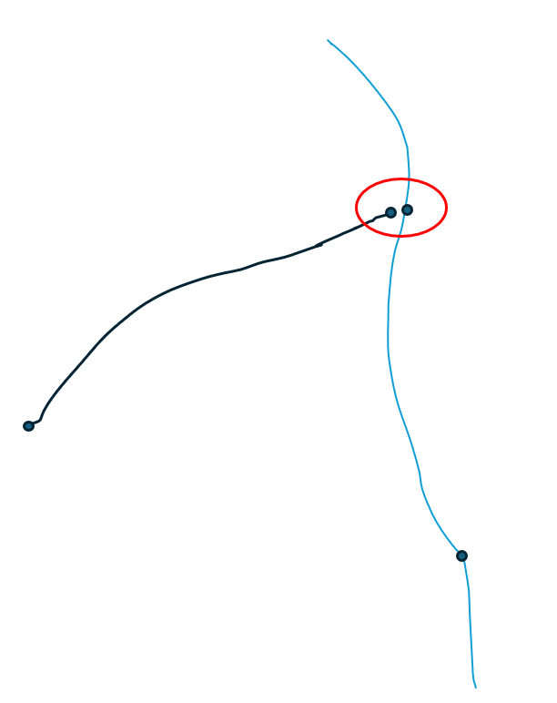
There are many issues caused by discretization, such as visually judging whether two identical circles overlap or whether two identical spheres overlap, which can lead to situations like the one shown in the image below. Another issue is rendering a smooth surface as if it has wrinkles. Another type of problem is mesh generation failure, which can cause holes to appear. Therefore, when holes are seen in the model, one needs to consider both the Mesh reasons and the model itself.
Next, we will introduce the generation, retrieval, and read/write methods of Mesh.
Although Mesh is necessary for rendering, it is not always required to use the kernel to generate Mesh for the model after it is constructed, because software with a GUI will generate the Mesh automatically for rendering. Normals in rendering are crucial information. If the Mesh does not provide normals, an approximate normal will be automatically calculated based on the Mesh during rendering. If it is necessary to ensure that the normals of the triangular mesh match those of the CAD model, the AMCAX::MakeShapeTool::EnsureNormalConsistency() can be used.
Quickly creating topological structures is a basic requirement, and functions like AMCAX::MakeVertex, AMCAX::MakeEdge, AMCAX::MakeWire, AMCAX::MakeFace, etc., provide quick creation methods for different topological structures. These are commonly used and important functionalities.
A Vertex can be created with a Point3:
AMCAX::MakeEdge can quickly create an Edge based on a Curve. If no Vertex is provided in the input for MakeEdge, it will automatically create two Vertices. This means that if you want to create two connected Edges using MakeEdge, you must pay attention to the shared Vertex. A simple construction will result in two Edges and four Vertices. Additionally, degenerated edges can also be created using MakeEdge. MakeEdge has many functionalities, and we will introduce them categorically:
You can create a line segment Edge using two Point3s or two TopoVertices. Note that the distance between the two Point3s/TopoVertices must be greater than AMCAX::Precision::Confusion(), otherwise, they will be considered the same Point3/TopoVertex.
For example, you can build it based on Line3, Circle3, etc. Here’s an example using Line3:
MakeEdge will automatically adjust parameters, Point3, and Vertex order based on the mathematical expression:
This is an important functionality for building Edges from curves. Here, MakeEdge will still automatically adjust parameters, Point3, and Vertex order, as well as Vertex orientation.
It is important to note that Edges created based on pcurve and Surface do not have 3D curves. Here's how you can construct them:
A wire can be constructed in the following two ways:
Note: Each edge added must geometrically connect to the edge that has already been added. For the example above, if the edges are added in the order e1—e3—e2—e4, when e3 is added, it will fail because it is not connected to e1. In this case, calling IsDone() will return false, and calling Error() will return WireError::DisconnectedWire. If it is known that the edges to be connected into a wire are connected, but the exact connection order is unknown, then the edge list method described below should be used.
The order of edges in the list will not affect the result of the wire construction.
Note: MakeWire can construct a wire that does not contain Seam Edges or degenerate edges. It supports adding individual edges or an edge list. MakeWire cannot correctly construct a wire containing degenerate edges because it determines orientation based on the 3D positions of the vertices, and degenerate edges have identical vertices, which may result in incorrect orientation. MakeWire also cannot correctly construct a wire containing non-manifold vertices, as this interface requires that the degree of vertices within a wire must be 2 (or 1, for open wire endpoints).
AMCAX::MakeFace has many functionalities, which we will introduce categorically:
t can be constructed based on mathematical expressions such as Plane, Cylinder, etc.:
Constructing a face from a Geom3Surface is the most common functionality of MakeFace:
MakeFace requires providing tolerance when providing a surface. It is important to note that if the input surface is infinite and there are no constrained parameter ranges, a wire will not be automatically generated. In other cases, a wire will be generated automatically.
When the wire lies on a plane, a face can be successfully constructed by directly inputting the wire:
Note: Inputting a wire that does not lie on a plane may result in failure.
Note: The final boolean parameter indicates whether the face region is inside the wire (true means inside).
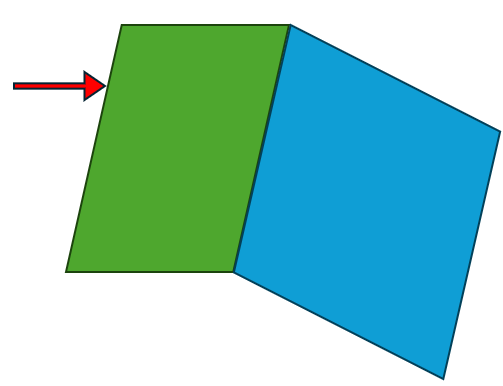
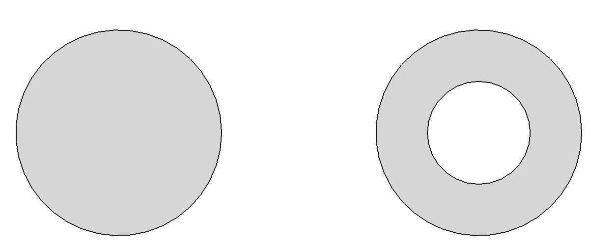
Adding a wire to an existing face:
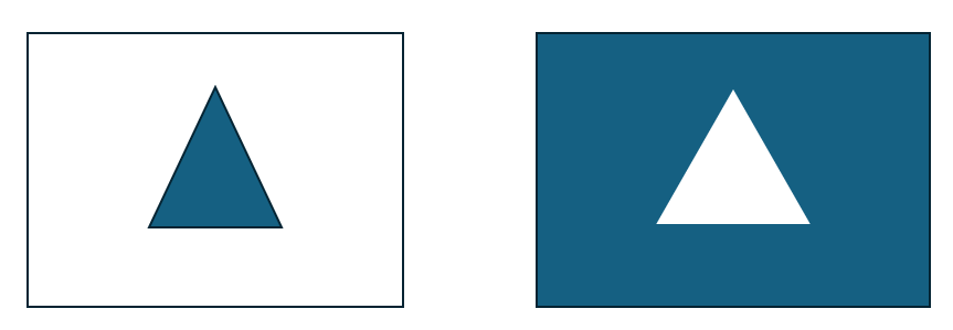
After execution, the result is as shown in the figure below: the left side is face7, and the right side is face8.
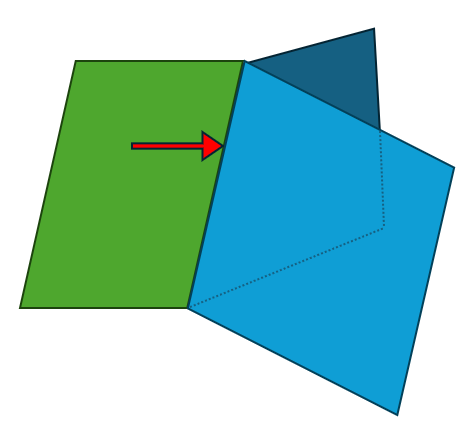
However, it is important to note the orientation of the wire. For example, if the code is written as below, it will produce an incorrect result:
The correct approach is to set the orientation of the edge or wire to Reversed at the edge or wire level.
Although Make*.hpp provides some convenient APIs for building TopoShapes, certain modeling problems can only be solved by TopoBuilder. In this section, we will introduce the methods for constructing different topological structures using TopoBuilder.
AMCAX::TopoBuilder::MakeVertex provides functionality to create a vertex.
There are different methods to build different types of edges. We will introduce them one by one:
The usual modeling approach is to calculate all the required Points, Curve3d, and PCurve using geometry, then build the topological structure:
Step 1: Prepare the Curve3d and construct the Edge using the curve.
AMCAX::TopoBuilder::Range sets the parameter range for the TopoEdge. If the parameter range of the curve matches the expected range of the edge, this step can be skipped.
Step 2: Prepare the start and end vertices and add them to the edge.
Note: Pay attention to the orientation of the start and end vertices. The orientation of the starting vertex is Forward, and the ending vertex is Reversed. The default orientation is Forward, so you need to change the orientation of the end vertex. There are two ways to do this: modify the orientation of the vertex itself or create a new one without modifying the original vertex. AMCAX::TopoShape::SetOrientation and AMCAX::TopoShape::Reverse modify the original vertex, while AMCAX::TopoShape::Oriented creates a new one and passes it to the builder.
Step 3: After constructing the Face, add the pcurve:
The direction of the pcurve should be consistent with the curve3d. The orientation of the edge does not affect the direction of the pcurve. Remember: "Geometry is geometry, topology is topology." The process of adding vertices can occur after creating the edge, so swapping steps 2 and 3 is fine. Adding vertices before calling Range is also acceptable.
The steps are mostly the same, but with a slight variation in step 3:
Note: The directions of pcurve1 and pcurve2 must remain consistent with the curve3d. pcurve1 corresponds to the Forward edge in the surface parameter domain, while pcurve2 corresponds to the Reversed edge in the surface parameter domain.
Other steps are the same, but step 1 is different, as there is no curve3d:
Make sure to set the degenerated flag to True. The direction of the pcurve does not need to match the curve3d, just the orientation of the edge.
The steps remain the same, but step 3 differs, where only one pcurve is used.
The standard approach is:
Step 1: Determine the direction of the Wire based on the parameter domain, and identify which edges to use and their orientations:
Step 2: Construct the Wire and add the edges:
The order in which edges are added can be arbitrary.
Step 3: Set the closed flag for the Wire:
To create a face, use the following method:
When constructing a shell, be mindful of the closed flag. The method is as follows:
To construct a solid, use this method:
To create a compound, use this method:
There are 4 types of OrientationType: Forward, Reversed, Internal, and External, with Forward and Reversed being the most commonly used. Any level of TopoShape can set its Orientation using SetOrientation() or retrieve its Orientation using Orientation(). If you want to get a TopoShape that only differs in Orientation from the current TopoShape, you can use Orientated().Orientation is independent of geometry and Location, meaning that changing one will not affect any other members.
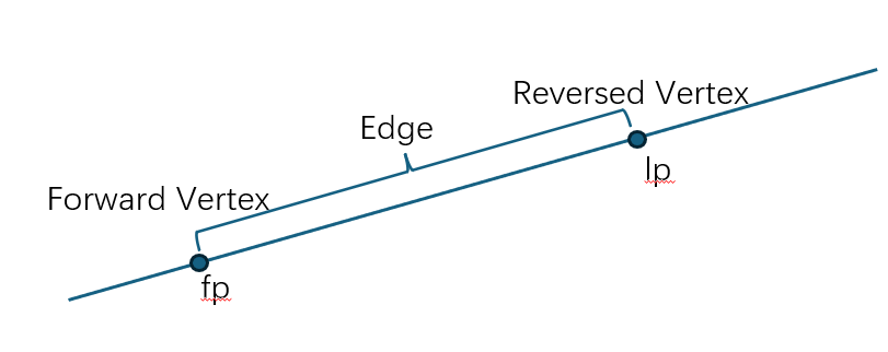
For an Edge, the Orientation of the starting Vertex is Forward, and the Orientation of the ending Vertex is Reversed. For example, a line segment Edge with two different Vertices will have one with Forward Orientation and the other with Reversed Orientation. Similarly, an Edge formed by a circle with two identical Vertices will still have one Vertex with Forward Orientation and the other with Reversed Orientation.
Note: In this example, because the Edge formed by a circle has two identical Vertices, only one vertex needs to be constructed. In this case, AMCAX::TopoTool::IsClosed(edge) will return true. If two vertices are constructed, AMCAX::TopoTool::IsClosed(edge) will return false.
The Forward direction of an Edge is the direction of curve3d. If there is no curve3d, it's the direction of the pcurve. The direction of a Reversed Edge is opposite to that of the curve.
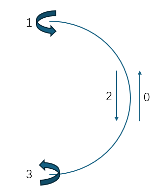
For example, given three Edges formed using 3d curves on the xoy plane and a Geom3Plane constructed using the natural frame:
Since the direction of the Wire must be counterclockwise in the parameter domain, Reversed Edge0, Forward Edge2, and Forward Edge1 should form the Wire.
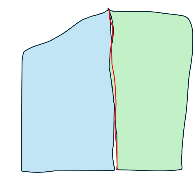
If a clockwise Wire is used, i.e., Forward Edge0, Reversed Edge1, and Reversed Edge2, the Face will define the region outside the Wire. Below are the counterclockwise and clockwise Wires:
If the Geom3Plane is constructed using Frame3(O, -OZ, OX), the Wire direction should be clockwise, i.e., Forward Edge0, Reversed Edge1, and Reversed Edge2, ensuring that the Face is correctly defined as the area enclosed by the Wire.
Reversing a Wire is equivalent to reversing the Orientation of each Edge in the Forward Wire.
Reversing a Face changes the direction of the region it encloses to the opposite of the surface normal. Reversing a Face is equivalent to reversing the Orientation of each Wire in the Forward Face.
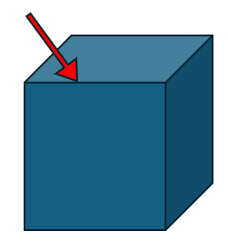
The method to retrieve the normal of the surface where the Face lies is as follows:
Reversing a Shell changes the direction of the region it encloses to the opposite direction. Reversing a Shell is equivalent to reversing the Orientation of each Face in the Forward Shell.
Reversing a Solid changes the direction of the region it encloses to the opposite direction. Reversing a Solid is equivalent to reversing the Orientation of each Face in the Forward Solid.
Tolerance represents the amount of error in a TopoShape. For example, a vertex on the curve of Edge1 is at Point3(0.0, 0.0, 0.0), and the same vertex on the curve of Edge2 is at Point3(1.0, 0.0, 0.0). With a tolerance of 2.0, these two points can be considered as the same point. In other words, although the geometric points of this vertex on different edges are different, it is still valid as a topological structure.
To obtain the Tolerance of a TopoShape, the method is: AMCAX::TopoTool::Tolerance(). Only structures containing geometric information, such as Vertex, Edge, and Face, have Tolerance. To change the Tolerance, the methods are: AMCAX::TopoBuilder::UpdateVertex(), AMCAX::TopoBuilder::UpdateEdge(), AMCAX::TopoBuilder::UpdateFace().
Next, we will introduce the Tolerance for Vertex, Edge, and Face in turn:
The Tolerance of a Vertex is a predefined value. Its significance is that when the distance from a Point to the Vertex (i.e., the distance from the Point to the Point within the Vertex) is less than or equal to the Tolerance, the Point is considered to lie on the Vertex. The Point in a Vertex can come from various sources: the Point3 itself, the value of a Curve at a certain parameter, or the value of a Surface at certain u,v parameters. The Tolerance of the Vertex must be no less than the maximum distance between these points.
The Tolerance of an Edge is a predefined value. Its significance is that when the distance from a Point to the Edge is less than or equal to the Tolerance, the Point is considered to lie on the Edge. Additionally, an Edge has a curve3d and a pcurve, where the pcurve can be used to construct an equivalent curve3d through a Surface. The maximum distance between multiple curve3d samples must not exceed the Tolerance of the Edge. If this condition is not met, the Tolerance of the Edge must be increased. Furthermore, the Tolerance of a Vertex must be greater than or equal to the Tolerance of the Edge it lies on.
The Tolerance of a Face is a predefined value. Its significance is that when the distance from a Point to the Face is less than or equal to the Tolerance, the Point is considered to lie on the Face. This is often used in Boolean operations. Additionally, the Tolerance of a Vertex or Edge must be greater than or equal to the Tolerance of the Face they lie on.
Note: When there is a dependency relationship, the Tolerance of a Vertex must be greater than or equal to the Tolerance of an Edge, and the Tolerance of an Edge must be greater than or equal to the Tolerance of a Face.
Whether a TopoShape is closed is a crucial flag. We can use AMCAX::TopoTool::IsClosed() to determine if a TopoShape is closed. This should be distinguished from AMCAX::TopoShape::Closed(), which returns a boolean flag that can be arbitrarily defined by the user. For example, even if a line segment is constructed into an Edge that is not closed, it can still be set as closed using AMCAX::TopoShape::Closed(true).
On the other hand, AMCAX::TopoTool::IsClosed() performs a topological check on certain types of TopoShape. Below is an explanation of how AMCAX::TopoTool::IsClosed() works for different ShapeType inputs.
AMCAX::TopoTool::IsClosed() is used to determine whether the FirstVertex and LastVertex of an Edge are the same (IsSame).
AMCAX::TopoTool::IsClosed() is used to determine whether a Wire has no boundary Vertex, meaning that each Vertex in the Wire appears an even number of times.
AMCAX::TopoTool::IsClosed() is used to determine whether a Shell has no boundary Edge (free Edge), meaning that each Edge in the Shell (excluding degenerate edges) appears an even number of times.
For TopoShape types other than Edge, Wire, and Shell, the result of AMCAX::TopoTool::IsClosed() is the same as the result of AMCAX::TopoShape::Closed().