Overview
This tutorial provides the basic usage of using polygonal meshes for subdivision surface modeling. Subdivision modeling generally starts with creating a primitive and generates a dense mesh approximation of a surface through stretching, transformation, subdivision, etc.
Construction of primitive shapes
The module supports the construction of various primitive geometries, for example, makeing a cube with a side length of 3 and dividing 2 segments in each direction. The code is as follows.
Class of PolyMesh API for make a cube.
Definition MeshMakeCube.hpp:15
Class of TMSpline structure The Low Level API functions are not exported for this version.
Definition PolyMesh.hpp:23
FrameT< double, 3 > Frame3
3D frame
Definition FrameT.hpp:885
You can also use the MeshMakeCone to construct a frustum with a base radius of 4, an upper radius of 2, and a height of 4. By default, it is divided into 8 segments along the rotation direction and 4 segments along the height direction
Class of PolyMesh API for make a cone.
Definition MeshMakeCone.hpp:15
Build a vortex model
Model Preview
This tutorial uses a simple vortex model to show some of the main modeling functions in the polymesh subdivision modeling module The model is shown in the figure below:
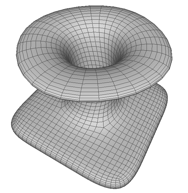
The vortex model
Using namespace
Namespace of all interface in the AMCAX SubD module.
Definition misc.docu:63
Namespace of all interface in the AMCAX kernel.
Definition misc.docu:8
Build Bottom mesh
Start by constructing a plane.
MeshMakeRectangle mkRect(frame, 3, 3, 3, 3);
PolyMesh* mesh = mkRect.BuildMesh();
Click here example1 to get the complete source code for the above example, which you can download according to your learning needs.
Extrude faces and apply transformations
Extrude the middle face to form a peak. Only change the topology, the new result is coincide the old result, and use MeshTransform to move the new result
std::vector<int> face_id = {4};
std::vector<int> face_id_new;
MeshExtrude::ExtrudeFace(mesh, face_id, face_id_new);
Apply translation and rotation transformations to the newly generated faces
MeshTransform trsfF;
trsfF.SetTransformation(trsfMove);
trsfF.TransformMeshFaces(mesh, face_id_new);
trsfF.SetTransformation(trsfRot);
trsfF.TransformMeshFaces(mesh, face_id_new);
constexpr const CoordType & Coord() const noexcept
Get the intrinsic coordinate of the direction.
Definition DirectionT.hpp:213
constexpr const DirectionT< Scalar, DIM > & Direction() const noexcept
Get the main direction (z direction) in 3D.
Definition FrameT.hpp:441
AxisT< double, 3 > Axis3
3D axis
Definition AxisT.hpp:423
TransformationT< double, 3 > Transformation3
3D transformation
Definition TransformationT.hpp:1102
VectorT< double, 3 > Vector3
3D vector
Definition VectorT.hpp:707
DirectionT< double, 3 > Direction3
3D direction
Definition DirectionT.hpp:587
PointT< double, 3 > Point3
3D point
Definition PointT.hpp:459
Click here example2 to get the complete source code for the above example, which you can download according to your learning needs.
Delete top face
Can freely delete any number of faces and leave holes
MeshReduce::DeleteFaces(mesh, face_id_new);
Click here example3 to get the complete source code for the above example, which you can download according to your learning needs.
Extrude edges and apply transformations
Extrude the edges left by the deleted face towards all sides to construct a new top faces.
std::vector<int> edgeid;
std::vector<int> edge_id_new;
for (int i = 0; i < mesh->numEdges(); ++i)
{
if (MeshCheck::IsEdgeBoundary(mesh, i))
{
int v0, v1;
MeshTool::EdgeVertexIndexs(mesh, i, v0, v1);
Point3 pv0 = MeshTool::Position(mesh, v0);
Point3 pv1 = MeshTool::Position(mesh, v1);
if (pv0.
Z() > 0.9 * h && pv1.
Z() > 0.9 * h)
{
edgeid.push_back(i);
}
}
}
MeshExtrude::ExtrudeEdge(mesh, edgeid, edge_id_new);
MeshTransform trsfE;
trsfE.SetTransformation(trsfScale);
trsfE.TransformMeshEdges(mesh, edge_id_new);
constexpr const Scalar & Z() const noexcept
Get z-coordinate of a point, only available when DIM >= 3.
Definition PointT.hpp:136
Click here example4 to get the complete source code for the above example, which you can download according to your learning needs.
Perform thickening
Thicken the shape to construct a solid.
MeshOffset::ThickenMesh(mesh, 0.2);
Click here example5 to get the complete source code for the above example, which you can download according to your learning needs.
Apply face split
Split the faces that connect the upper and lower parts with significant changes makes the results smoother. By split loop an edge, all faces that are topologically parallel to that edge are split in half.
for (int i = 0; i < mesh->numEdges(); ++i)
{
int v0, v1;
MeshTool::EdgeVertexIndexs(mesh, i, v0, v1);
Point3 pv0 = MeshTool::Position(mesh, v0);
Point3 pv1 = MeshTool::Position(mesh, v1);
if (std::fabs(pv1.
Z() - pv0.
Z()) > 0.8 * h)
{
MeshSplit::SplitLoop(mesh, i);
i = 0;
}
}
Click here example6 to get the complete source code for the above example, which you can download according to your learning needs.
Set crease edge features
You can select some edges to set the sharpness level, which is between 0 and 1. The larger the value, the sharper the final shape will be at the edge. When the value is greater than 1, the final result will show sharp feature edges
std::vector<int> edgeidCrese;
for (int i = 0; i < mesh->numEdges(); ++i)
{
int v0, v1;
MeshTool::EdgeVertexIndexs(mesh, i, v0, v1);
Point3 pv0 = MeshTool::Position(mesh, v0);
Point3 pv1 = MeshTool::Position(mesh, v1);
{
edgeidCrese.push_back(i);
}
}
std::vector<double> creaseLevel(edgeidCrese.size(), 1.0);
MeshCreaseTool::AddCreaseEdge(mesh, edgeidCrese, creaseLevel);
auto Distance(const PointT< OtherScalar, DIM > &other) const noexcept
Compute the Euclidean distance from the other point.
Definition PointT.hpp:180
Do Subdivision
This module provides two subdivision methods, the Catmull-Clark subdivision supports arbitrary meshes, the Loop subdivision only supports triangular meshes. The subdivided shape can still be edited again.
MeshSubdivideHE::CatmullClark(mesh, 3);
Save Mesh
This module provides the option to save result as OBJ files and OFF files
std::string fileNameOBJ = "sampleResult.obj";
PolyMeshIO::WriteMesh(fileNameOBJ, mesh);
Click here example7 to obtain the complete source code of the polygonal mesh subdivision modeling example, you can download it according to your learning needs.
Appendix
The complete code of this sample is listed here:
void MakeTornado()
{
double h = 2;
MeshMakeRectangle mkRect(frame, 3, 3, 3, 3);
PolyMesh* mesh = mkRect.BuildMesh();
std::vector<int> face_id = {4};
std::vector<int> face_id_new;
MeshExtrude::ExtrudeFace(mesh, face_id, face_id_new);
MeshTransform trsfF;
trsfF.SetTransformation(trsfMove);
trsfF.TransformMeshFaces(mesh, face_id_new);
trsfF.SetTransformation(trsfRot);
trsfF.TransformMeshFaces(mesh, face_id_new);
MeshReduce::DeleteFaces(mesh, face_id_new);
std::vector<int> edgeid;
std::vector<int> edge_id_new;
for (int i = 0; i < mesh->numEdges(); ++i)
{
if (MeshCheck::IsEdgeBoundary(mesh, i))
{
int v0, v1;
MeshTool::EdgeVertexIndexs(mesh, i, v0, v1);
Point3 pv0 = MeshTool::Position(mesh, v0);
Point3 pv1 = MeshTool::Position(mesh, v1);
if (pv0.
Z() > 0.9 * h && pv1.
Z() > 0.9 * h)
{
edgeid.push_back(i);
}
}
}
MeshExtrude::ExtrudeEdge(mesh, edgeid, edge_id_new);
MeshTransform trsfE;
trsfE.SetTransformation(trsfScale);
trsfE.TransformMeshEdges(mesh, edge_id_new);
MeshOffset::ThickenMesh(mesh, 0.2);
for (int i = 0; i < mesh->numEdges(); ++i)
{
int v0, v1;
MeshTool::EdgeVertexIndexs(mesh, i, v0, v1);
Point3 pv0 = MeshTool::Position(mesh, v0);
Point3 pv1 = MeshTool::Position(mesh, v1);
if (std::fabs(pv1.
Z() - pv0.
Z()) > 0.8 * h)
{
MeshSplit::SplitLoop(mesh, i);
i = 0;
}
}
std::vector<int> edgeidCrese;
for (int i = 0; i < mesh->numEdges(); ++i)
{
int v0, v1;
MeshTool::EdgeVertexIndexs(mesh, i, v0, v1);
Point3 pv0 = MeshTool::Position(mesh, v0);
Point3 pv1 = MeshTool::Position(mesh, v1);
{
edgeidCrese.push_back(i);
}
}
std::vector<double> creaseLevel(edgeidCrese.size(), 1.0);
MeshCreaseTool::AddCreaseEdge(mesh, edgeidCrese, creaseLevel);
MeshSubdivideHE::CatmullClark(mesh, 3);
std::string fileNameOBJ = "sampleResult.obj";
PolyMeshIO::WriteMesh(fileNameOBJ, mesh);
delete mesh;
}
Class of PolyMesh check Tool.
Class of PolyMesh API for extrude method.
Class of PolyMesh API for make a plane rectangle.
Class of PolyMesh API for Thicken a Mesh.
Class of PolyMesh API for Reduce a Mesh.
Class of PolyMesh API for split mesh.
Class of PolyMesh API for mesh subdividion, which will use half-edge data structure to modify the mes...
Class of PolyMesh API for load and write a polymesh.