AMCAX Kernel
Geometry kernel for CAD/CAE/CAM
|
AMCAX Kernel 1.0.0.0
|
|
AMCAX Kernel 1.0.0.0
|
This tutorial provides detailed configuration methods for using mesh generation and 2D boundary layers.
The boundary layer mesh generation creates a denser mesh distribution in regions near solid surfaces to better capture fluid velocity profile variations and viscous effects.
Input: Selected boundaries; Output: Boundary layer mesh (quadrilateral elements).
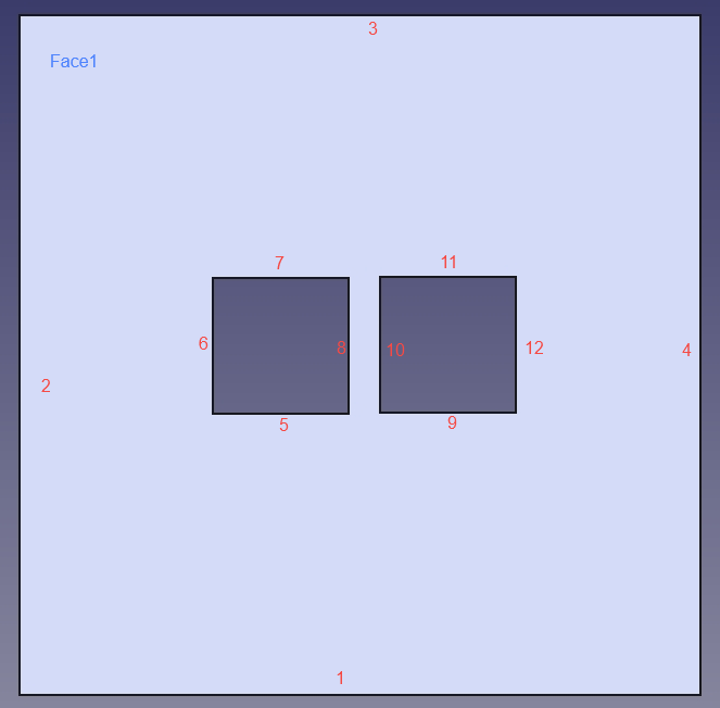
The STEP format CAD models and their edge and face numbering are shown in the following figures. These models will be used in this tutorial.
Model 1:
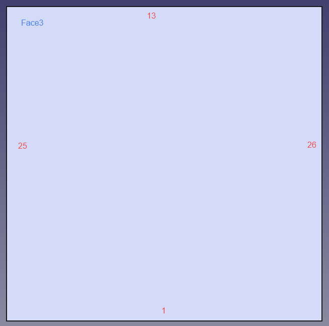
Model 2:
Below is the basic JSON configuration. For more complex configurations, please refer to complex JSON template.
| Class | key | Required | Value Range | Default | Notes |
|---|---|---|---|---|---|
| BoundaryLayer | EntityType | Yes | [Face, Edge] | — | |
| BoundaryLayer | EFPairs/SelectedEntities | Yes | — | ||
| BoundaryLayer-Basic | GrowthRate | Yes | "Constant"、"Variable" [1.0,2.0] | — | "Constant": Uses a fixed growth rate value for all layers, maintaining the same expansion ratio between consecutive layers. "Variable": Uses an array of growth rates, allowing different expansion ratios for each layer transition. |
| BoundaryLayer-Basic | InitLayerHeight | Yes | Absolute:[eps,MaxSize] Aspect:[eps,1] | — | "Absolute": Initial layer height remains constant across the entire boundary layer, regardless of local mesh characteristics. "Aspect": Initial layer height is calculated as a factor multiplied by the local surface mesh length, adapting to local mesh size. |
| BoundaryLayer-Basic | NLayers | Yes | [1,inf] | — | |
| BoundaryLayer-Basic | ProblematicAreasTreatment | Yes | STOP、SQUEEZE、COLLAPSE、EXCLUDE | — | STOP:When boundary layer generation encounters issues, stop the process. SQUEEZE:Squeeze layers to overcome intersection, proximity, or quality issues. COLLAPSE:Collapse layers in local regions to overcome intersection, proximity, or quality issues. EXCLUDE:Exclude problematic local regions to overcome intersection, proximity, or quality issues. |
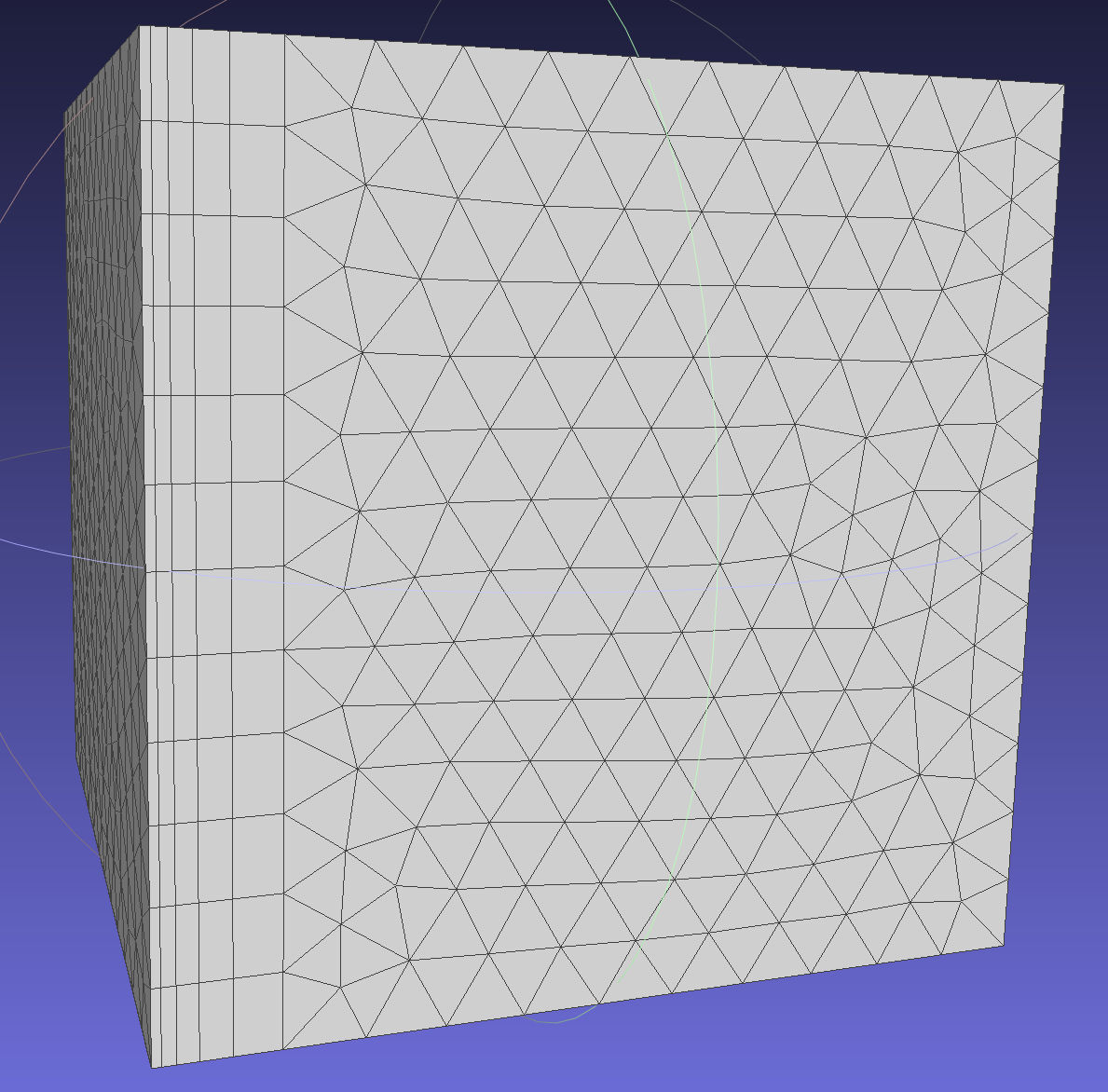
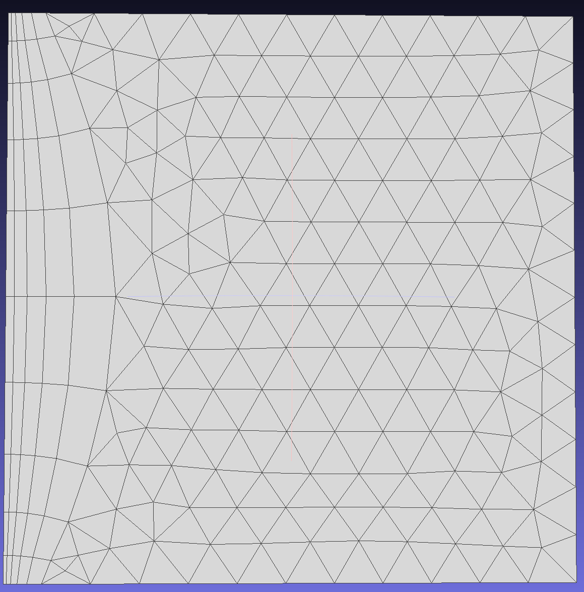
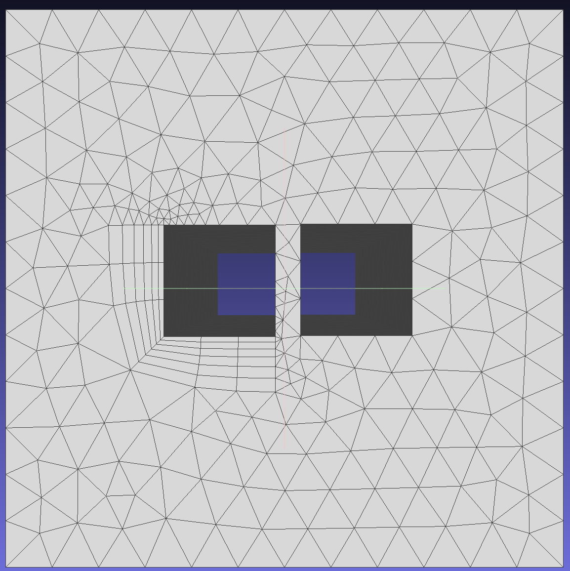
Generates quadrilateral mesh elements growing from selected boundary edges into the face interior, as shown in the figure below.
"EntityType": "Edge" indicates 2D boundary layer generation from edges into faces. Specifies growth direction from source edge to target face. Example: growth from edge (tag=25) to face (tag=3). Note: The edge must be a boundary edge of the face.
Absolute Mode: Fixed initial layer height for all nodes, independent of local surface mesh size (in contrast to Aspect mode). (Standard initial layer height reference: https://www.cfd-online.com/Tools/yplus.php).In Aspect mode, the value is a factor of the local surface mesh length, and the first layer height is defined by multiplying the local surface mesh size.
To show the mesh generation effect in both Absolute and Aspect modes, add a Linear distribution in the basic JSON example:
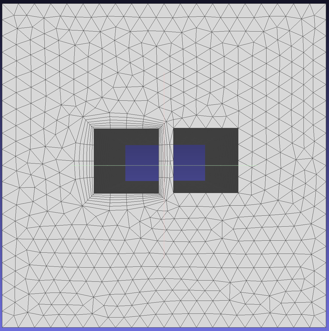
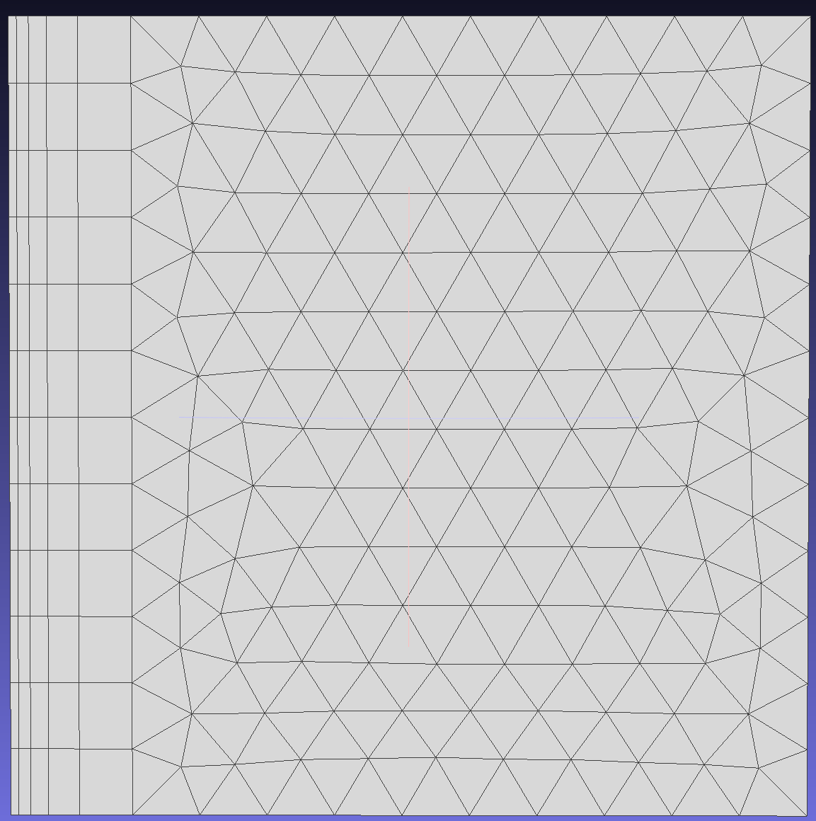
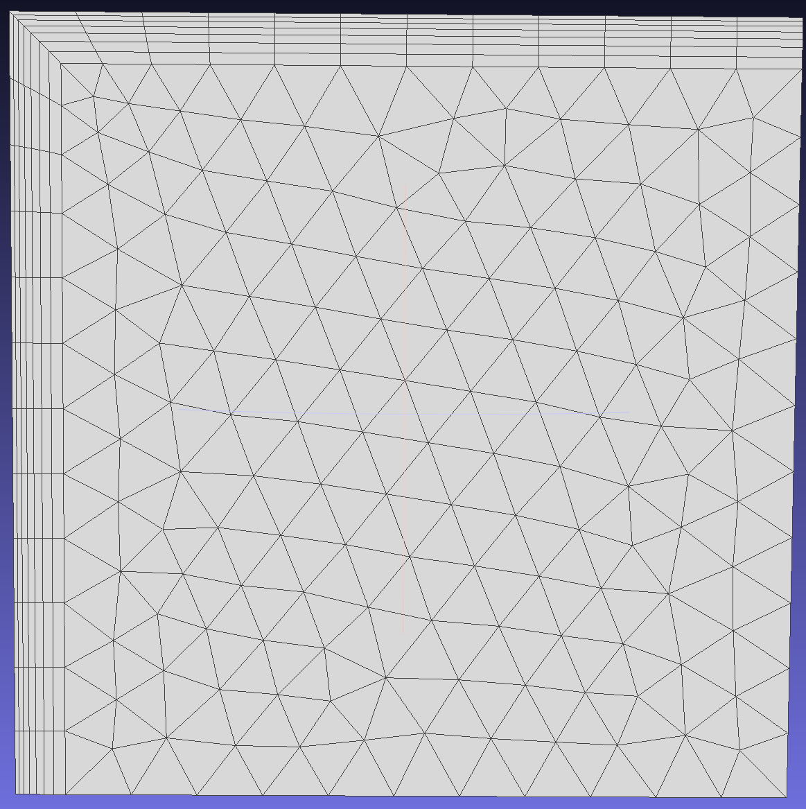
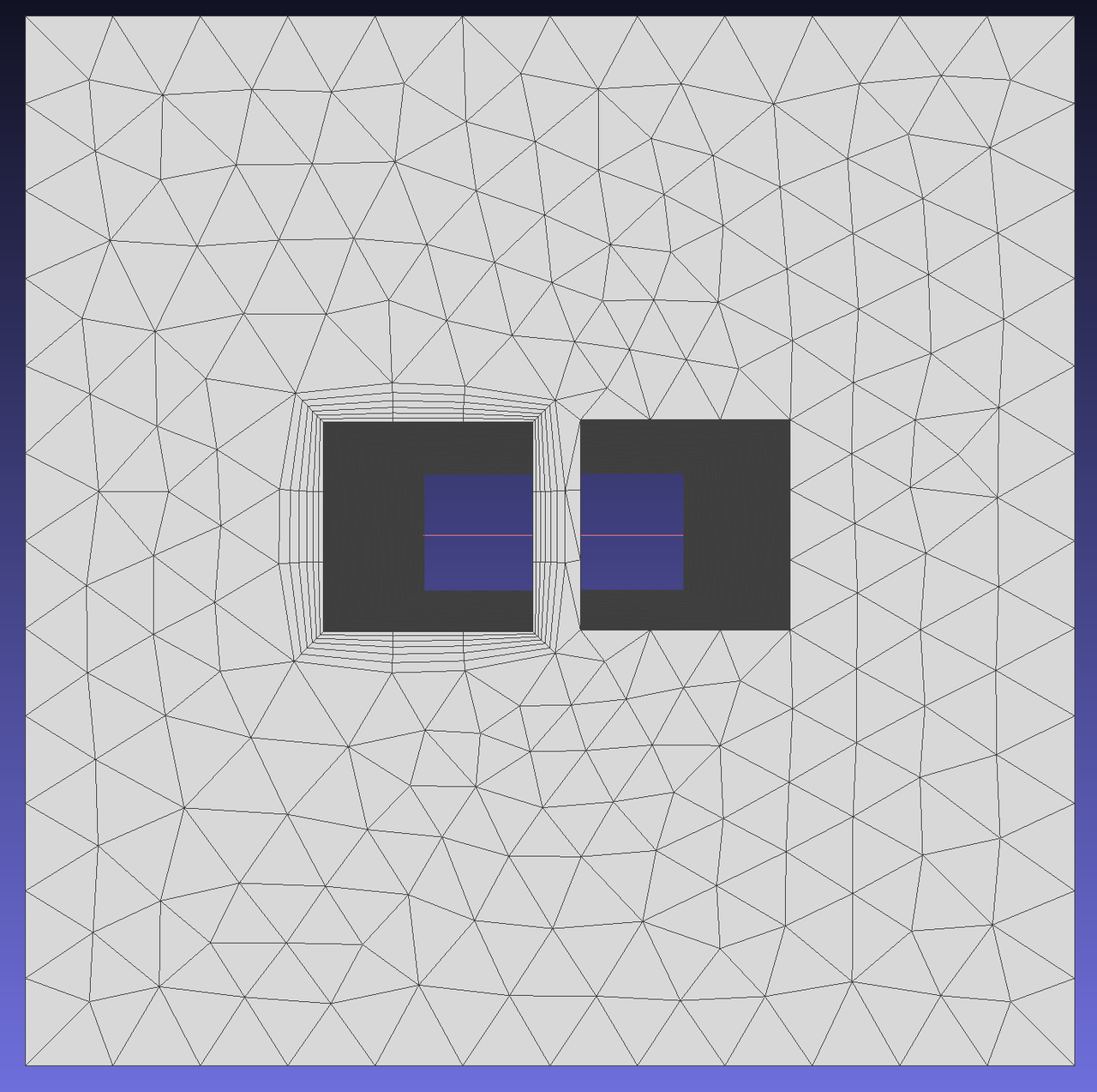
When the initial layer height is in Absolute mode, as shown in the result below, the initial layer height of each node does not change with the local mesh size.
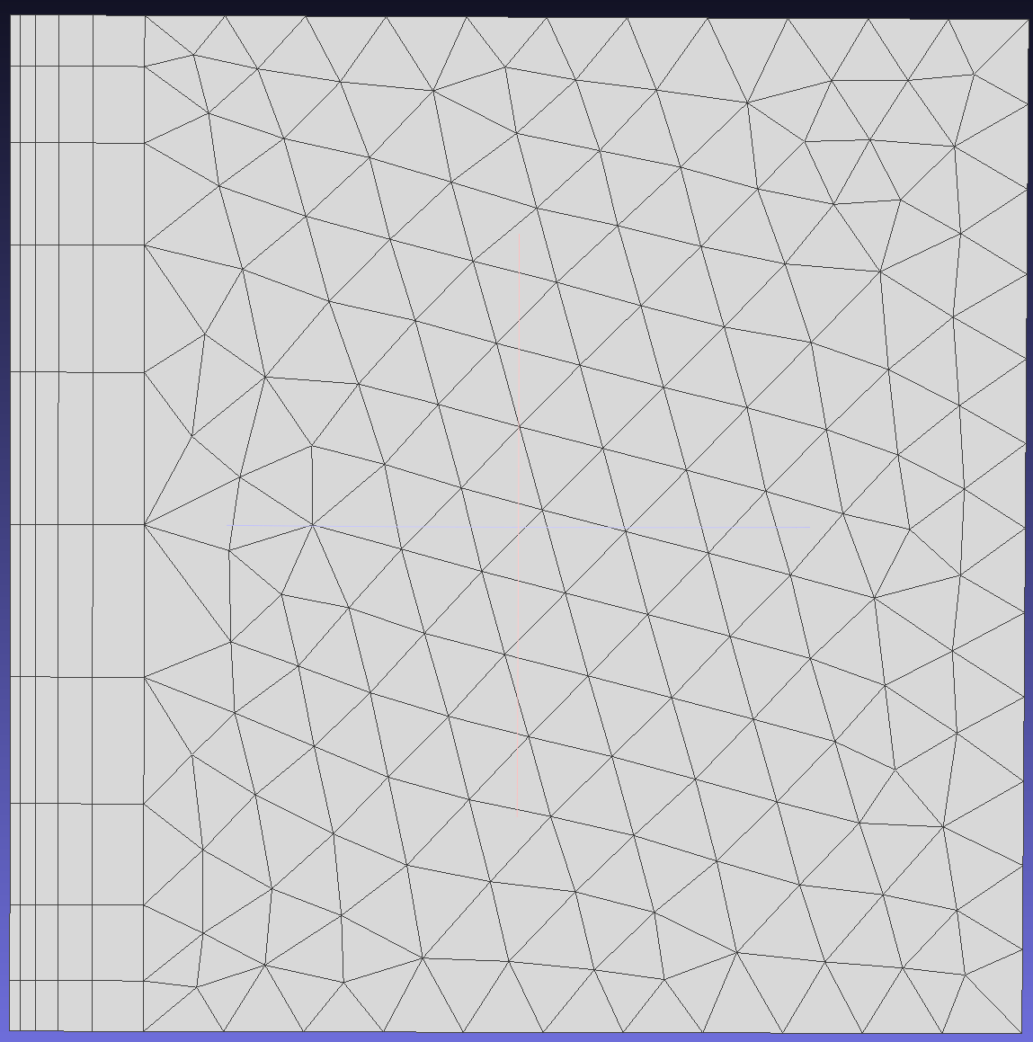
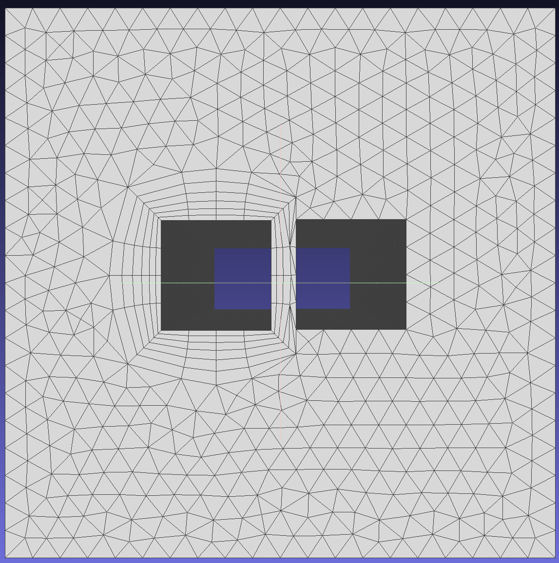
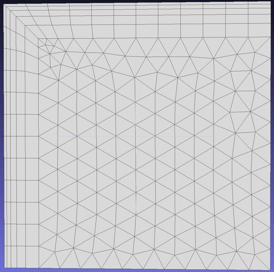
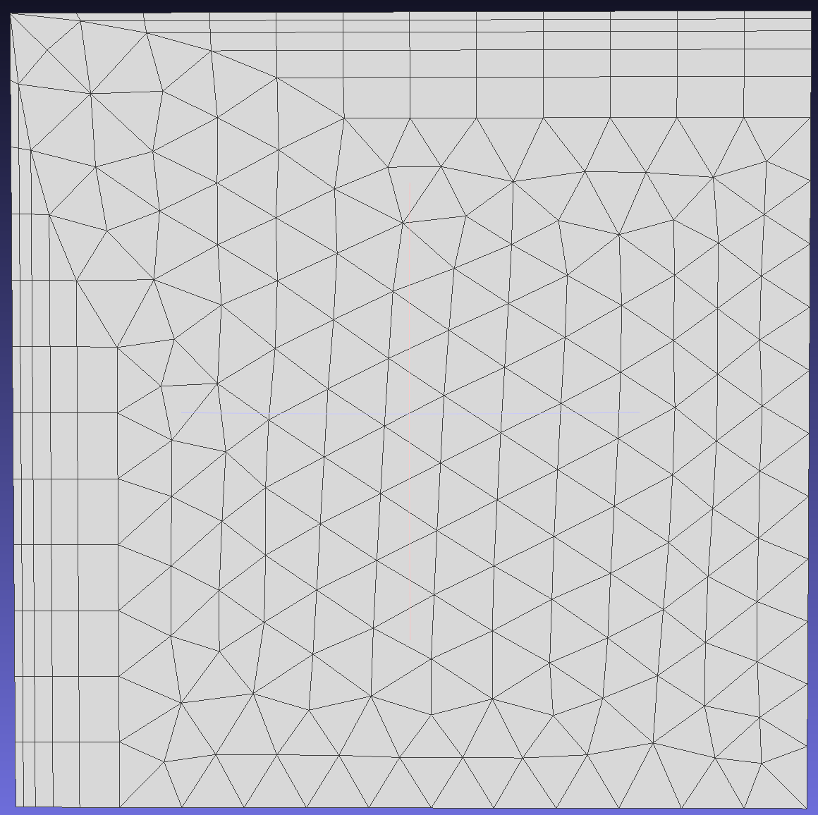
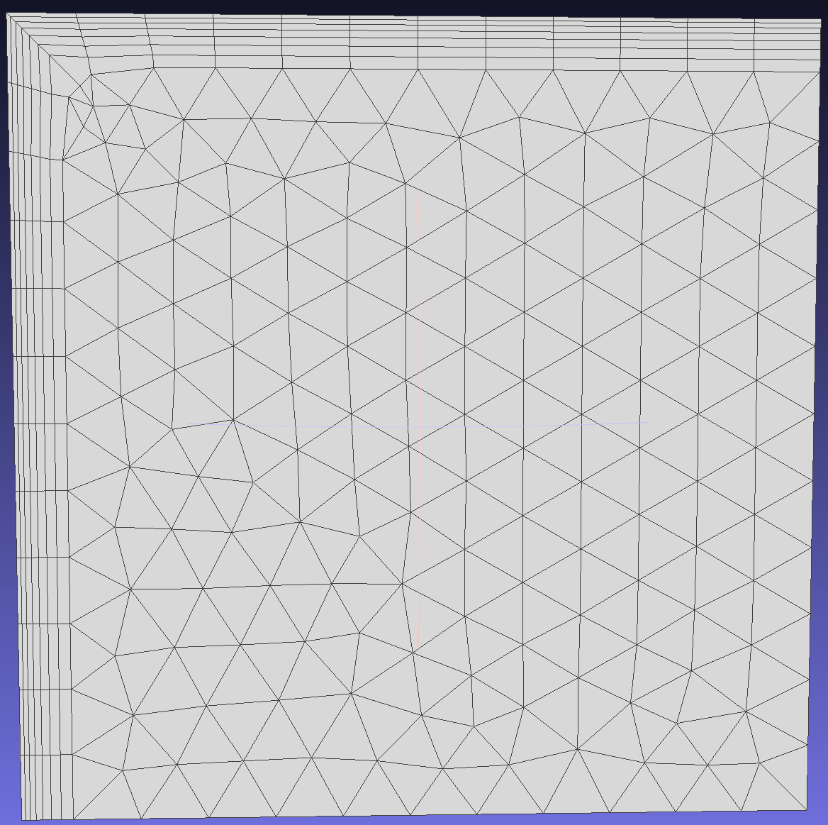
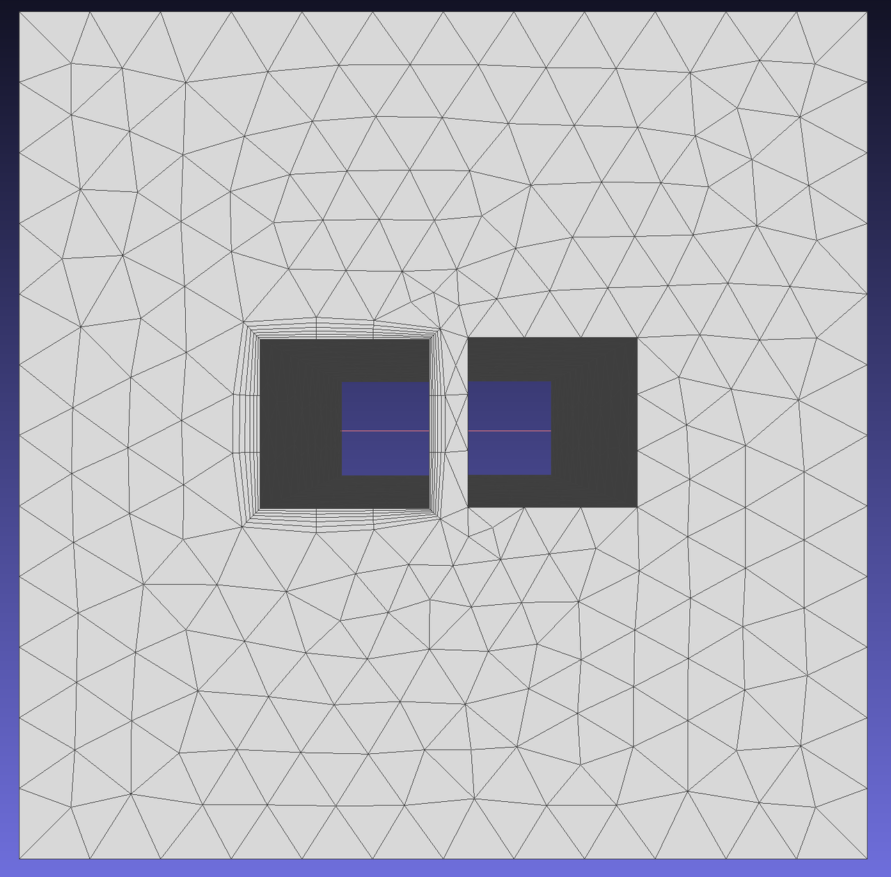
When the initial layer height is in Aspect mode, as shown in the result below, the initial layer height of each node changes with the local mesh size, and its value is h0 = size * Aspect.
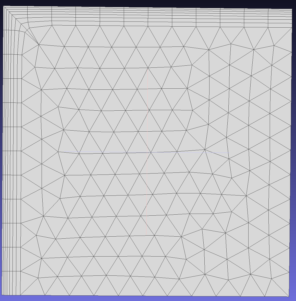
Constant growth rate, the growth rate factor for each layer is the same (the next layer is larger than the previous one).
Variable growth rate, starting from the second layer, the growth rate for each layer is independent (note that the growth rate for the first layer is always 0, and it matches the number of layers).
NLayers:Specifies the desired number of boundary layer mesh.
Methods used when layers cannot be generated due to local geometric features or insufficient space for growing all required layers.To show the effect of different methods on mesh generation, modify EFPairs.
1.When boundary layer generation encounters issues, stop the process.
2.Squeeze layers to overcome intersection, proximity, or quality issues.
3.Collapse layers in local regions to overcome intersection, proximity, or quality issues.
4.Exclude problematic local regions to overcome intersection, proximity, or quality issues.
| Class | key | Required | Value Range | Default | Notes |
|---|---|---|---|---|---|
| BoundaryLayer-Basic | AdditionalOuterLayers | No | [0,inf] | 0 | Additional outer layers to match the last boundary layer with nearby element size |
| BoundaryLayer-Basic | LastAspect | No | [eps,1] | 0 | Last layer aspect ratio, active when additional layers are non-zero |
| BoundaryLayer-SideTreatment | CollapseFreeEdges | No | true、false | false | Enables collapsing at free edges, active only in "COLLAPSE" mode |
| BoundaryLayer-VectorTreatment | SmoothTopCapShellMesh | No | true、false | true | Allows vectors to deviate from original normal position; otherwise grows orthogonally |
| BoundaryLayer-VectorTreatment | SmoothVectors | No | true,[0,180] false | [true,90] | Maximum allowable angle deviation from initial position |
| BoundaryLayer-VectorTreatment | SeparateVectors | No | true,[eps,180] false | false | Separates boundary layer vectors at sharp edges (user-specified angle between faces) |
| BoundaryLayer-VectorTreatment | SeparateNumber | No | [0,inf] | 0 | Number of vectors to separate at sharp edges |
| BoundaryLayer-GrowthControls | MiniFirstLayerHeight | No | [0,inf] | 0 | Enable only in "SQUEEZE" mode, minimum allowed first layer height, defaults to 5% of initial height when set to 0 |
| BoundaryLayer-GrowthControls | MaxLayerAspect | No | true,[eps,inf] false | false | Enable only in "SQUEEZE" mode, maximum aspect ratio |
| BoundaryLayer-GrowthControls | ProximityCheckFactor | No | true,[eps,inf] false | false | Proximity check factor, controls the minimum gap between two opposing boundary layer regions |
| BoundaryLayer-GrowthControls-SQUEEZE | MiniLayerAspect | No | true,[eps,inf] false | false | Minimum aspect ratio, active only when "ProximityCheckFactor" is enabled and in "SQUEEZE" mode |
AdditionalOuterLayers: The number of additional boundary layers to match the last boundary layer with nearby triangular cell sizes. If the size of the last boundary layer is larger than the nearby triangular cell size, even if this parameter is set, it will default to 0.
LastAspect: Aspect ratio of the last layer, configurable only when AdditionalOuterLayers is non-zero.
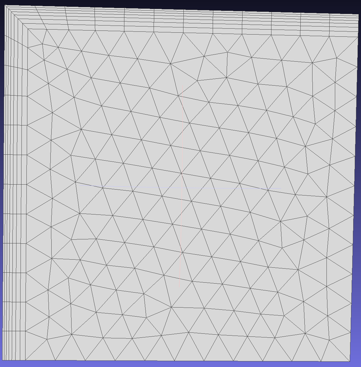
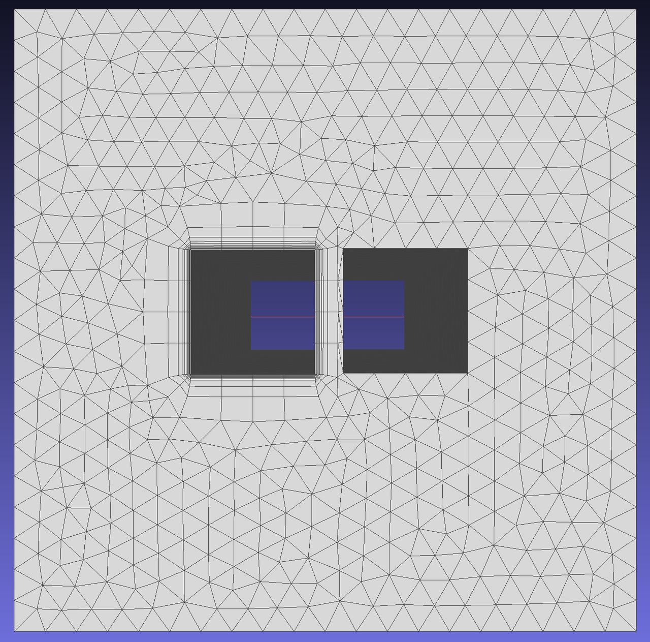
The boundary layer mesh is generated on edge 25 of face 3, and the results are as follows:
Allow collapsing at free edges when the angle between two faces exceeds a certain value, gradually reducing mesh layers near face intersection lines.
Select edges 25 and 26 on face 3 to generate boundary layer meshes to observe the free edge collapsing function.
When enabled, this option allows growth vectors to deviate from their original normal positions. If disabled, layers grow orthogonally. This operation enables more layers to be generated as the mesh expands more in enclosed regions, though it may result in lower quality (less orthogonal) elements.
To clearly see the difference, adjust the initial layer height and thickness of the boundary layer.
When enabled, users can specify the maximum allowable angle deviation from the original normal position. This operation allows more layers to be generated as the mesh expands in enclosed regions, though it may result in lower quality (less orthogonal) elements.
Separates boundary layer vectors at sharp edges (where the angle between two faces is user-specified). When disabled, boundary layers remain unsplit, resulting in a continuous layer mesh around sharp edges but with skewed elements. When enabled, the generated mesh has better quality elements, but the exposed sides will be meshed with triangular elements.
To demonstrate the effect of this function, generate boundary layer meshes on edges 5 and 6 of face 1. Since the angle between edges 5 and 6 is 270 degrees, consider separating the boundary layer vectors at this location.
Minimum allowed height when squeeze is activated. If not specified (=0), the first layer height may compress to 5% of initial height before switching to COLLAPSE mode.
Maximum allowed aspect ratio when squeeze is activated. In absolute mode, layers may overgrow in areas with small surface element lengths, potentially becoming very tall. After specifying maximum aspect ratio, layer height remains constant once the allowed ratio is reached.
Enable this option to control the minimum gap between opposing boundary layer regions. The minimum distance between boundary layers is defined as the proximity check factor multiplied by the sum of opposing mesh sizes. This option is crucial for ensuring sufficient space for generating high-quality triangular meshes.
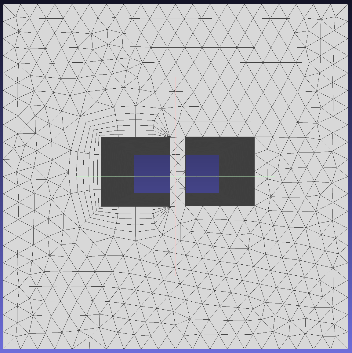
To demonstrate the effect of this function, generate boundary layers on edges 5, 6, 7, and 8 of face 1. Since the boundary layer generated by edge 8 may intersect with edge 10, select SQUEEZE mode and set this parameter to control the minimum gap between regions.
When squeeze is activated with specified ProximityCheckFactor, defines maximum allowed aspect ratio for boundary layers. If the boundary layer's aspect ratio becomes less than this value with specified ProximityCheckFactor, the boundary layer will compress to the allowed minimum ratio before switching to COLLAPSE mode.
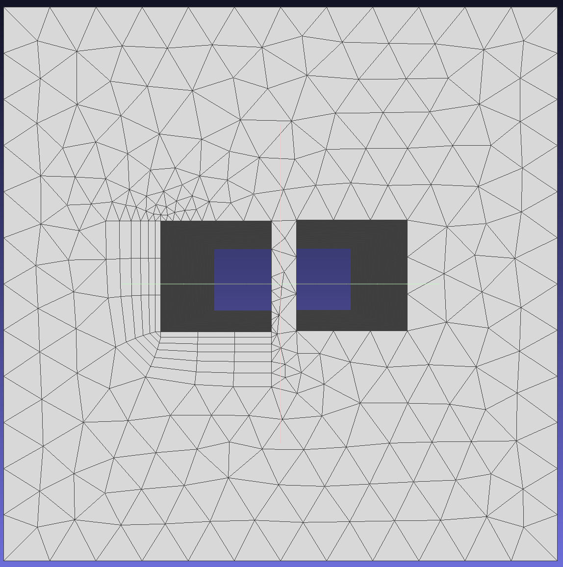
Now boundary layer mesh needs to be generated from edges 5, 6, 7, 8 towards face 1. At right angles, we want to have 3 normal directions, so under VectorTreatment, SeparateVectors is set to [true, 270] and SeparateNumber is set to 2. The generated boundary layer with these parameters may contact edge 10, so the problem area treatment method is set to COLLAPSE mode.
Result:
Click here example02 to get the full source code of the 2D boundary layer detailed JSON example. Everyone can download it as needed.