AMCAX Kernel
Geometry kernel for CAD/CAE/CAM
|
AMCAX Kernel 1.0.0.0
|
|
AMCAX Kernel 1.0.0.0
|
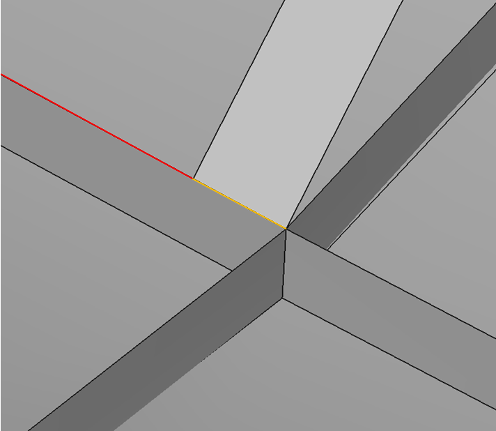
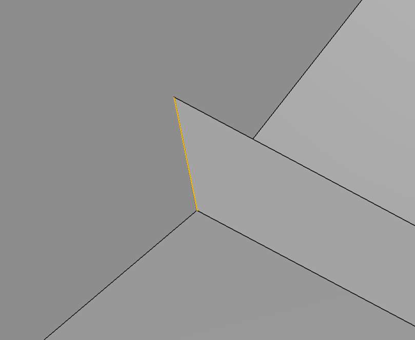
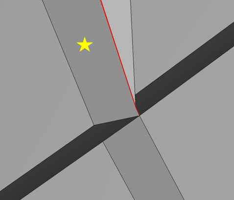
This tutorial provides the basic usage of geometry editing, including importing brep format files and performing geometric editing operations on the model using the GeomE API for model repair. The tutorial also utilizes the API from the AMCAX kernel. Additionally, in the images of this tutorial, the red edge represents free edge, while the yellow edge represents manifold edge.
To keep the example code clear, namespaces are used.
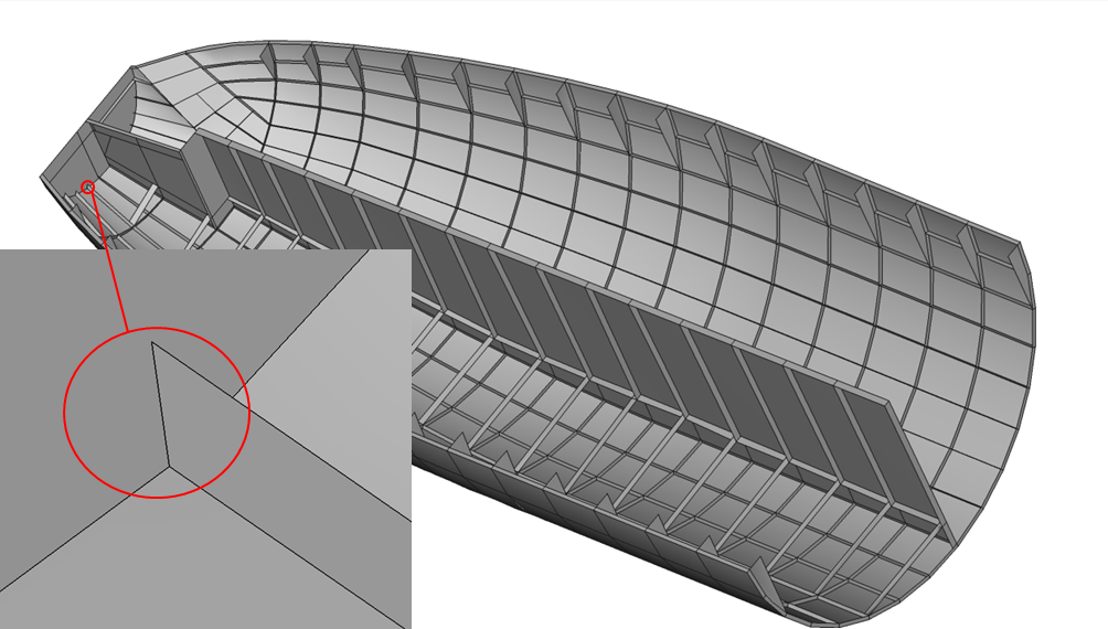
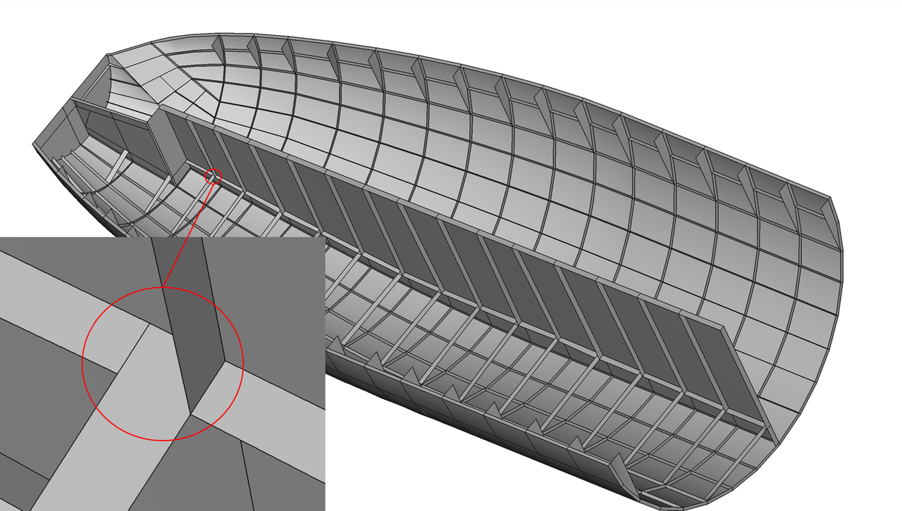
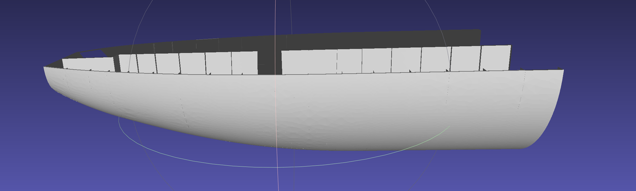
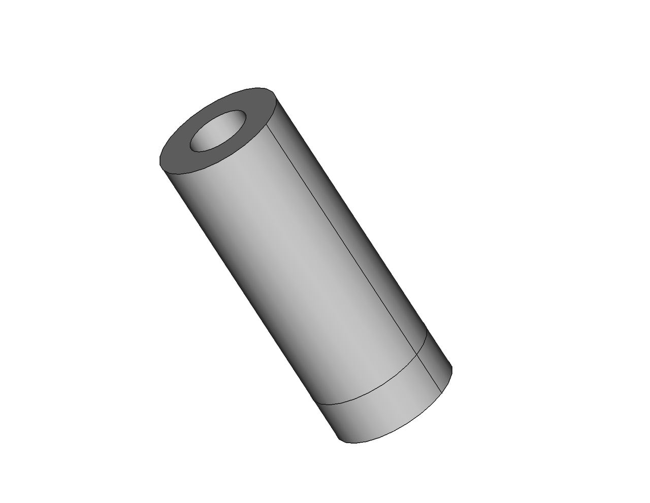
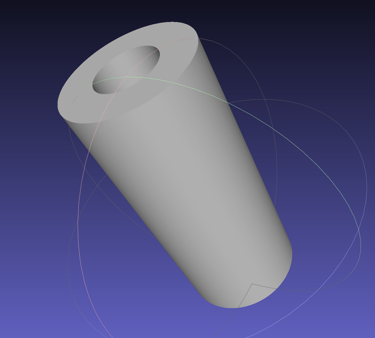
Import a brep format CAD model, as shown in the figure below:
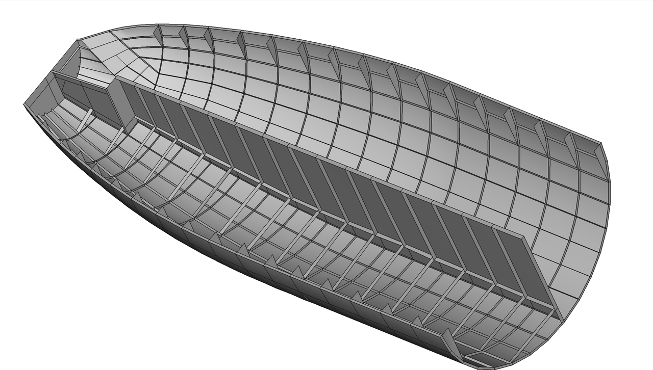
This tutorial example will first read in a brep model, then perform geometric editing operations on the input model, and finally write the model into a BREP file.
Import the CAD file and construct the model.
Write to brep file.
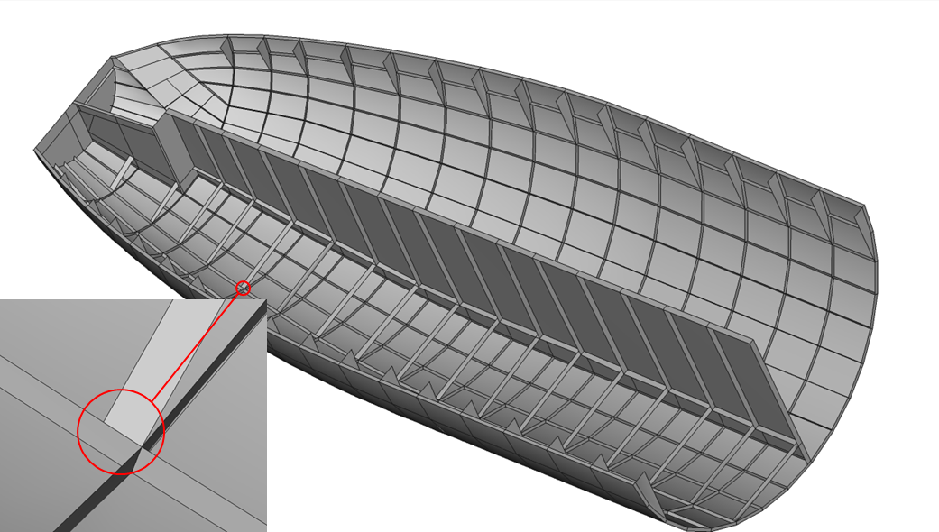
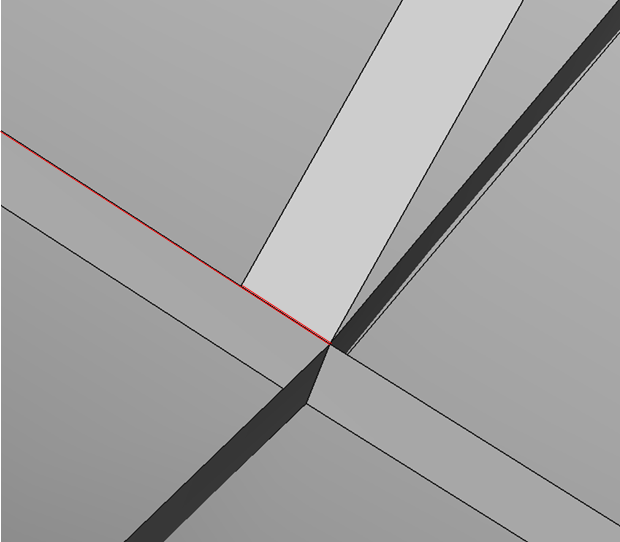
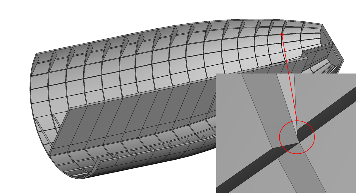
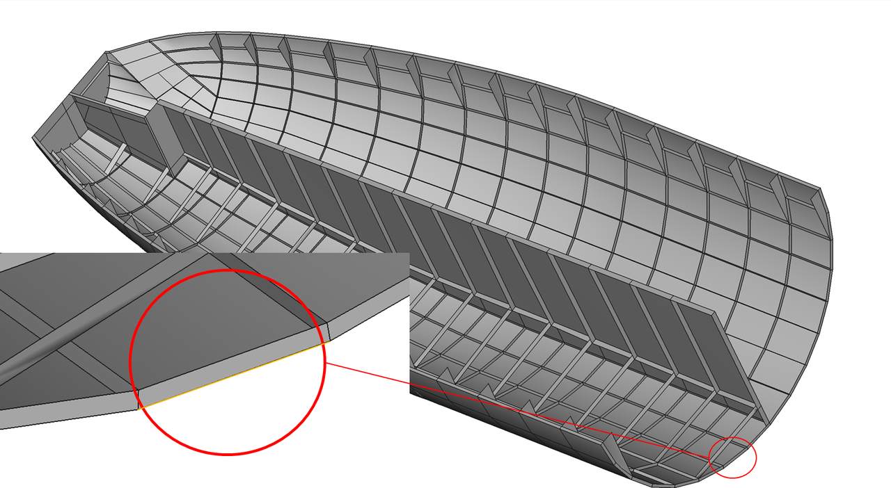
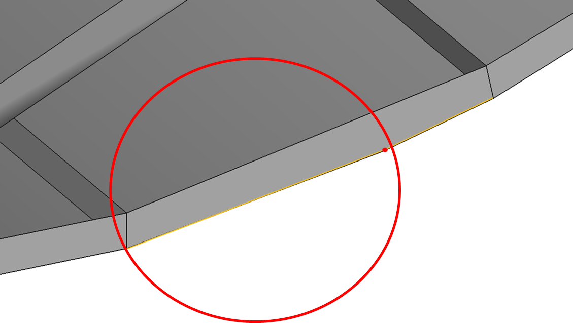
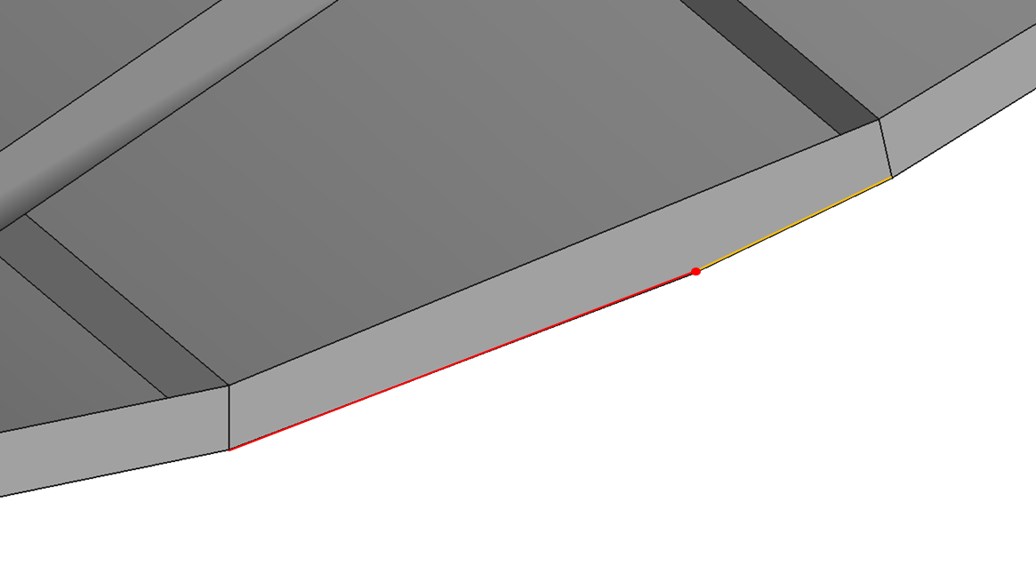
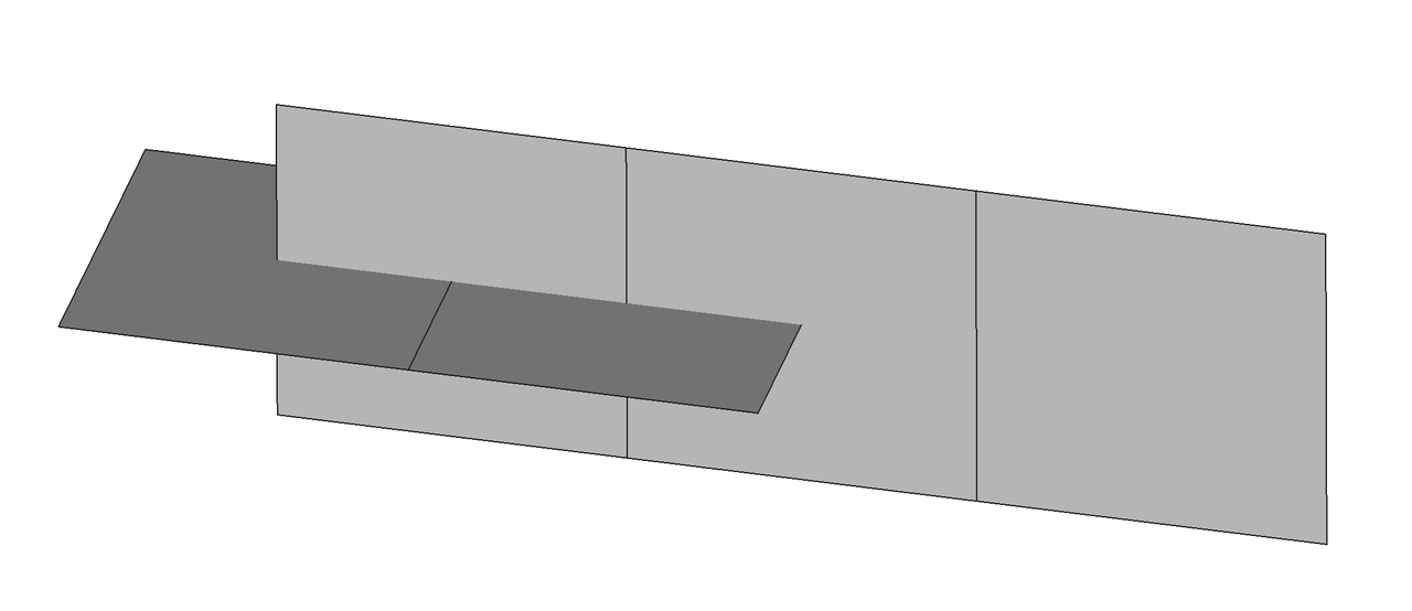
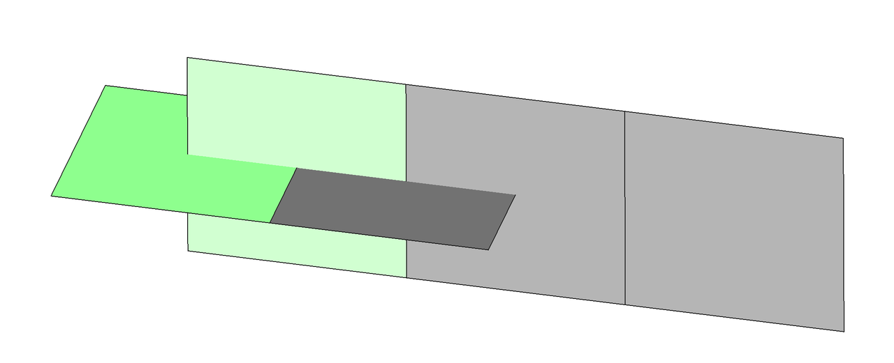
As shown in the figure, the area marked with a red circle has a gap between the short edge of one face and the long edge of another face. Both edges are free edges.
 |  |
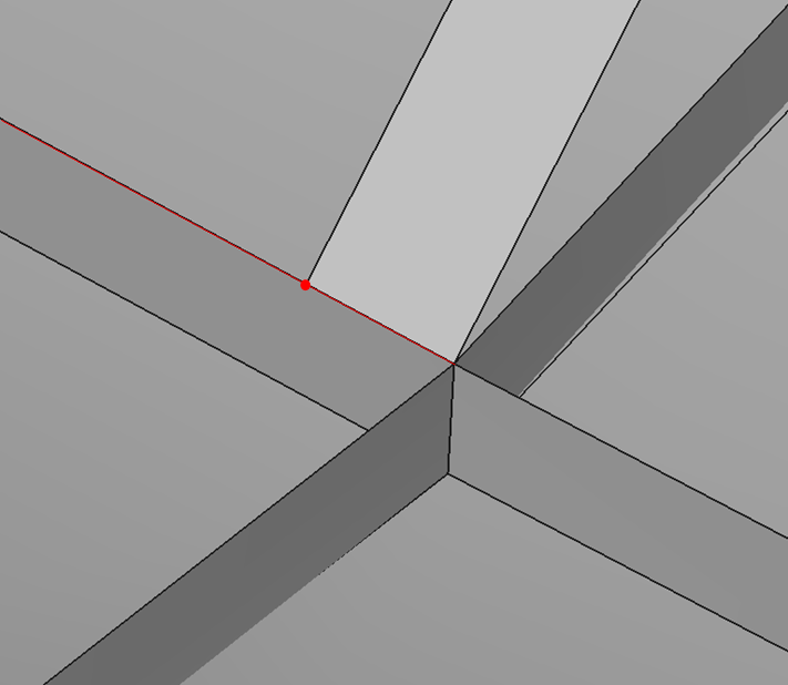
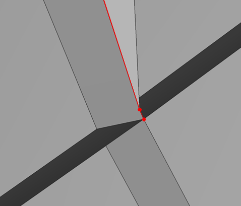
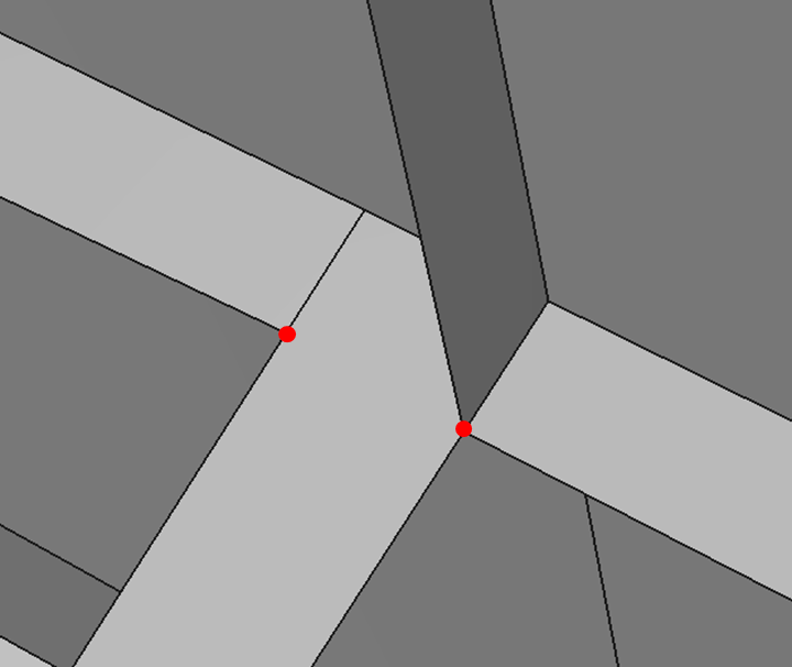
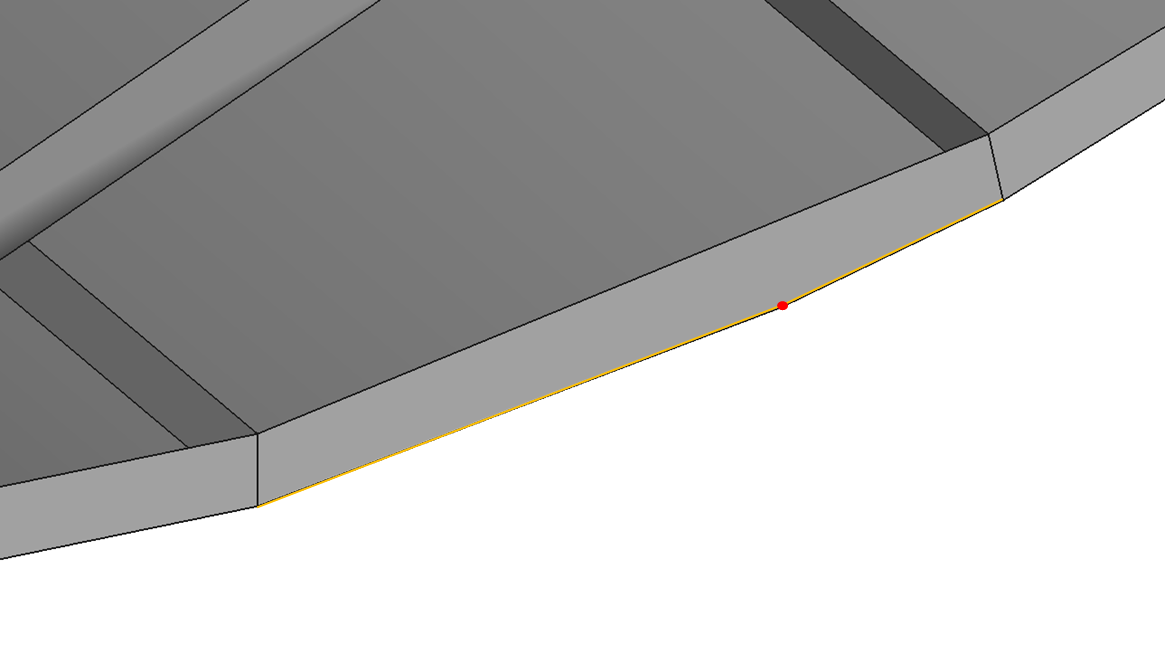
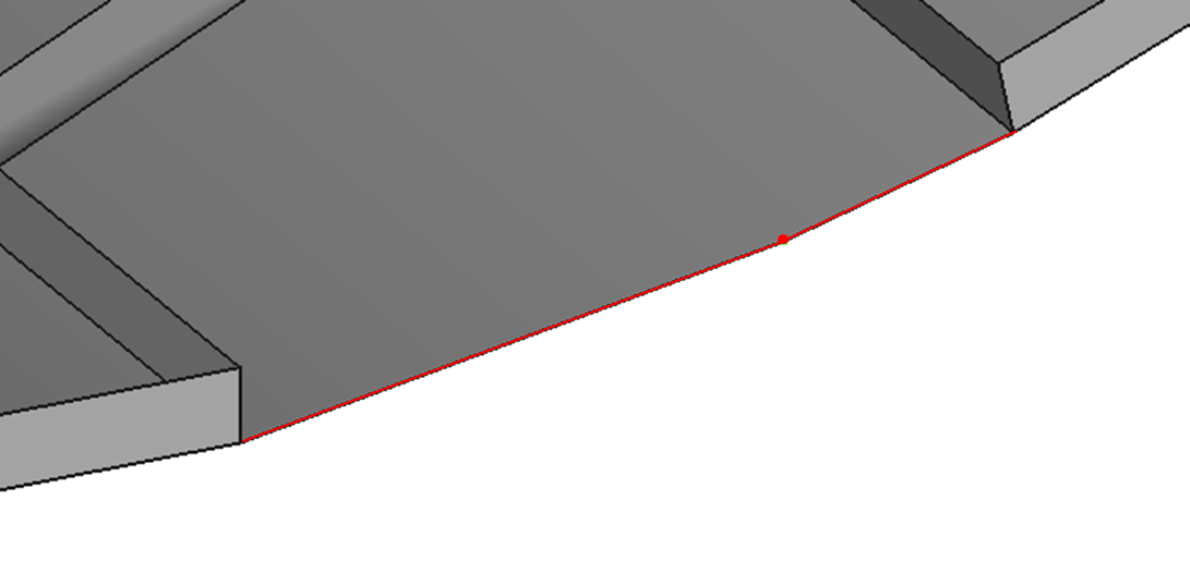
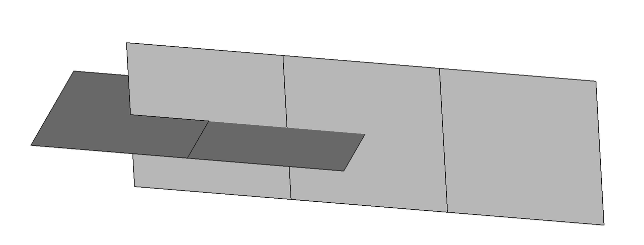
As shown in the figure, the point has been inserted into the corresponding edge, and the long edge has been split into two edges.
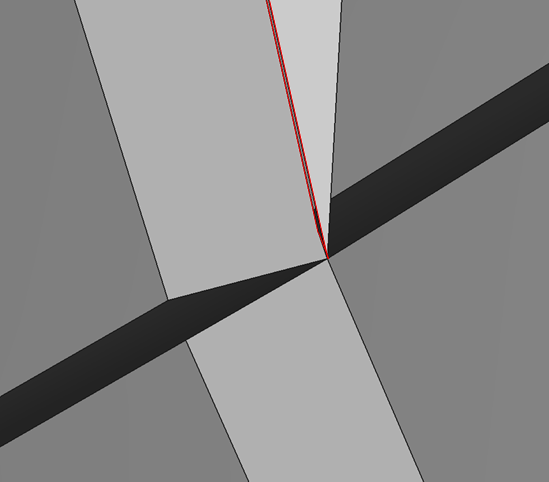
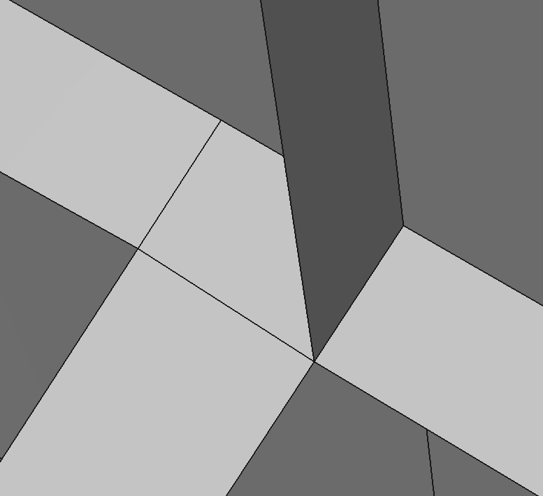
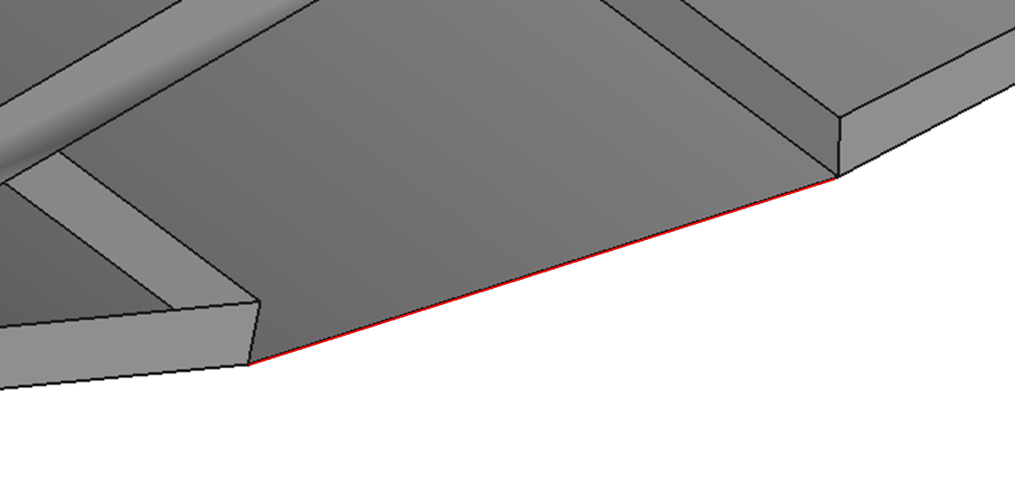
As shown in the figure, the gap between the two faces has been eliminated.
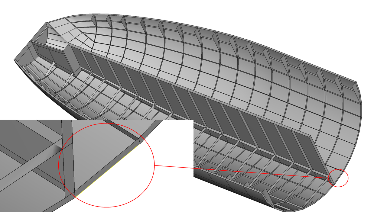
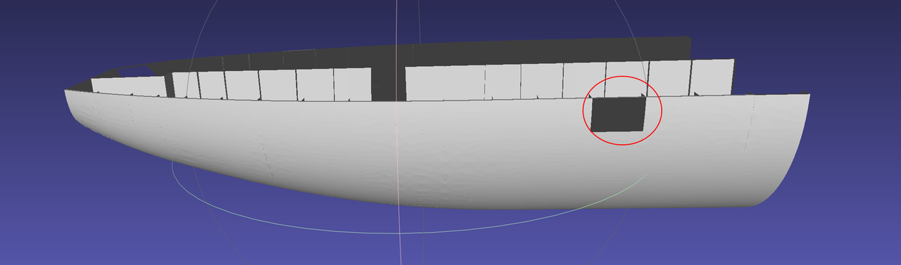
As shown in the figure, the area marked with a red circle has a gap between the edge of one face and another face.
 |  |
As shown in the figure, the specified edge has been projected onto the interior of the face.
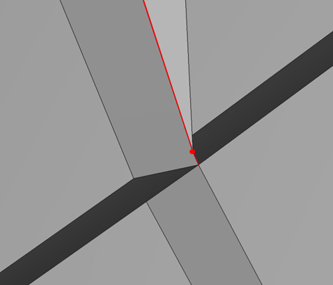
As shown in the figure, in the area marked with a red circle, a very short edge has appeared.
 |  |
As shown in the figure, the vertex has been released onto the respective faces.
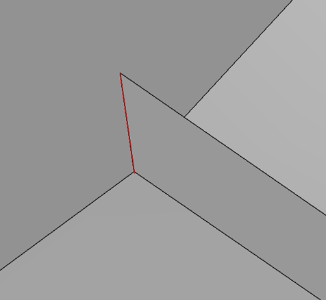
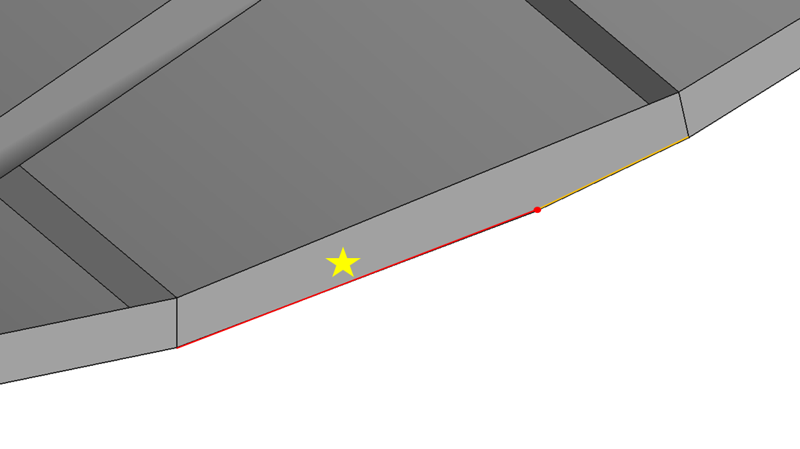
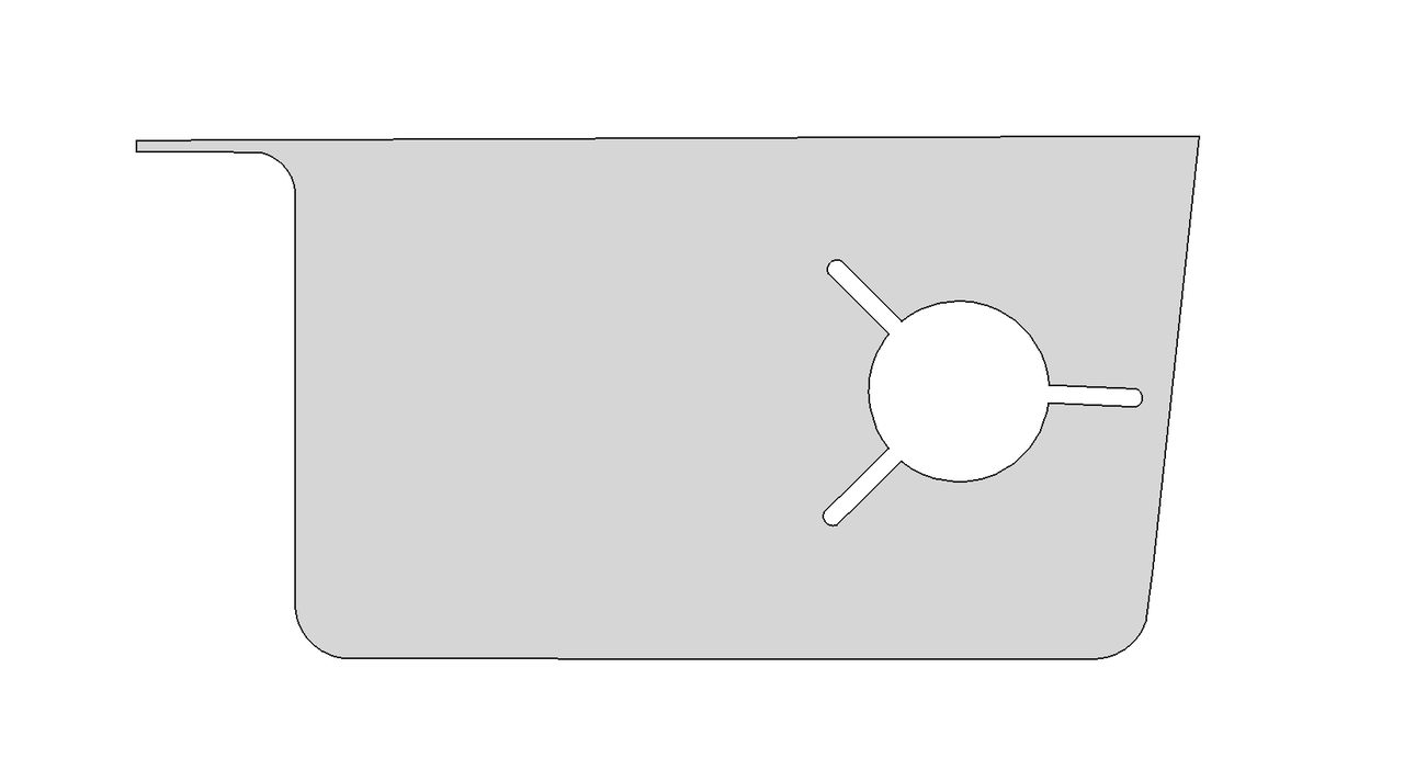
Delete the red vertex of the star-shaped marked face.
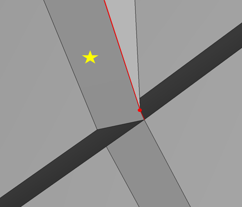
As shown in the figure, the red vertex of the star-shaped marked face has been deleted, and the long edge and short edge are now connected as a single edge.
As shown in the figure, the vertex of the face on the right needs to be sewn to the vertex of the face on the left.
As shown in the figure, the two vertices have been sewn together.
As shown in the figure, the edge of the left face is stitched to the edge of the right face.
As shown in the figure, select the two vertices to perform parameter cut on the face.
 |  |
As shown in the figure, the parameter cut was successful.
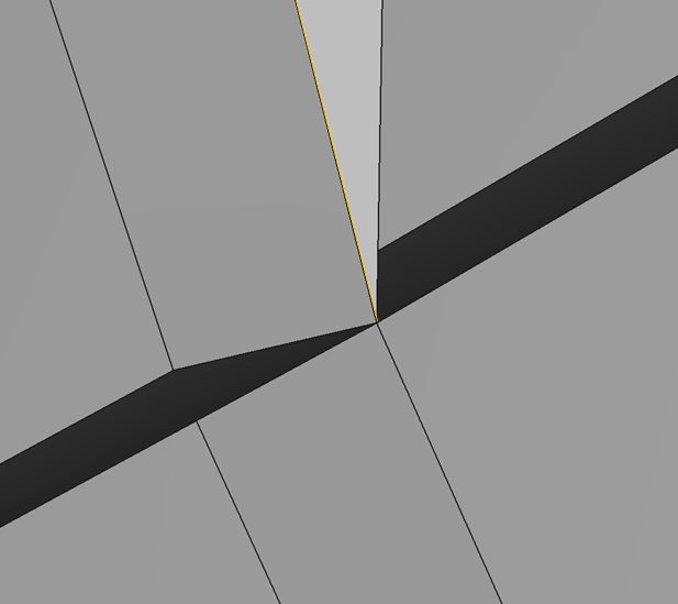
As shown in the figure, you can select an edge (yellow) for rebuilding.
The following are the edge before rebuilding and the edge after rebuilding.
As shown in the figure, insert a vertex at a ratio of 0.3 on the selected edge (yellow).
As shown in the figure, a vertex has been inserted at 0.3 of the selected edge.
As shown in the figure, release the edge circled in red.
As shown in the figure, the selected edge has been released onto two faces, becoming free edges.
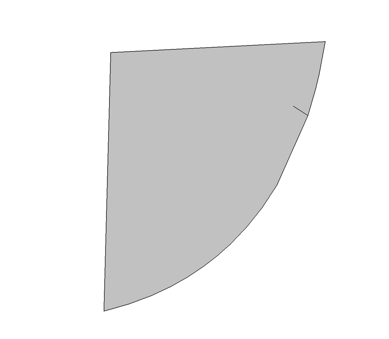
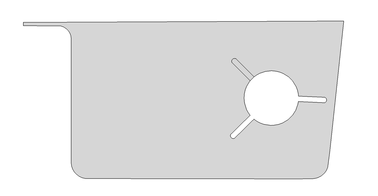
As shown in the figure, the star-marked face needs to be deleted.
As shown in the figure, the selected face has been deleted.

As shown in the figure, join the two red edges.
As shown in the figure, after the joint, the two edges become one edge, and the vertex disappears.
 |  |
Click here example01 to get the full source code of the geometry edit example one. Everyone can download it as needed.
The complete code for this example is listed below:
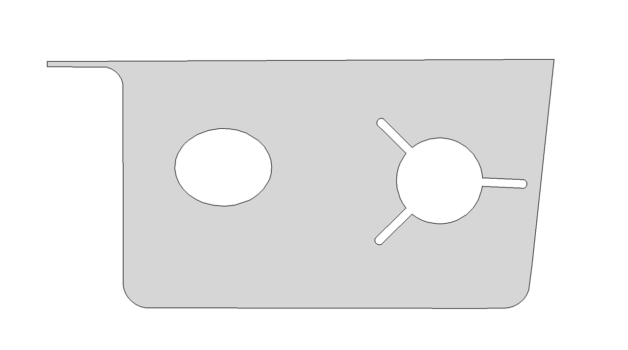
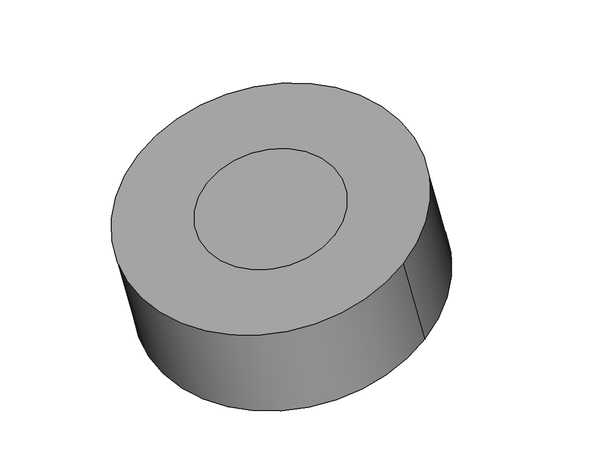
Import a STEP format CAD model, as shown in the figure below:
In this tutorial example, the STEP model will first be read in, followed by geometric editing operations on the input model, and finally, the model will be written to a BREP file.
Import the CAD file and build the model.
Write the model to a BREP file.
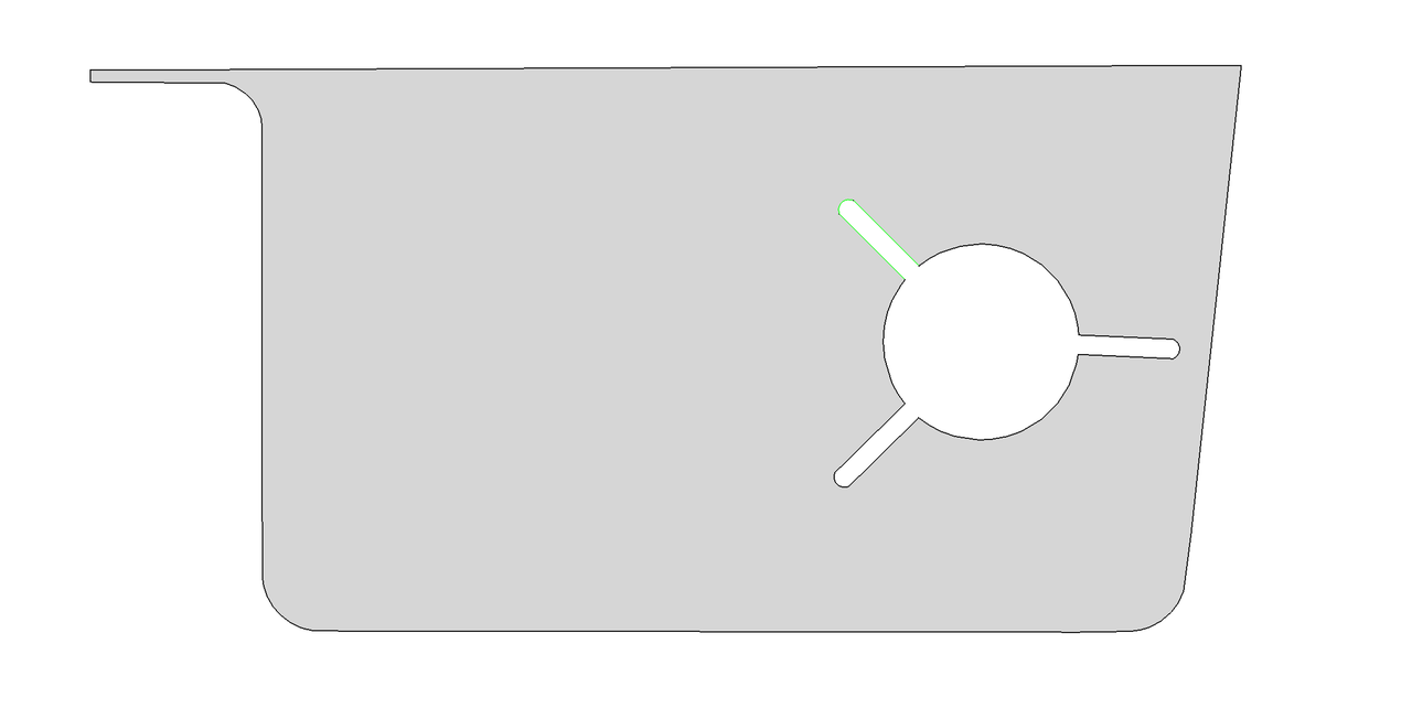
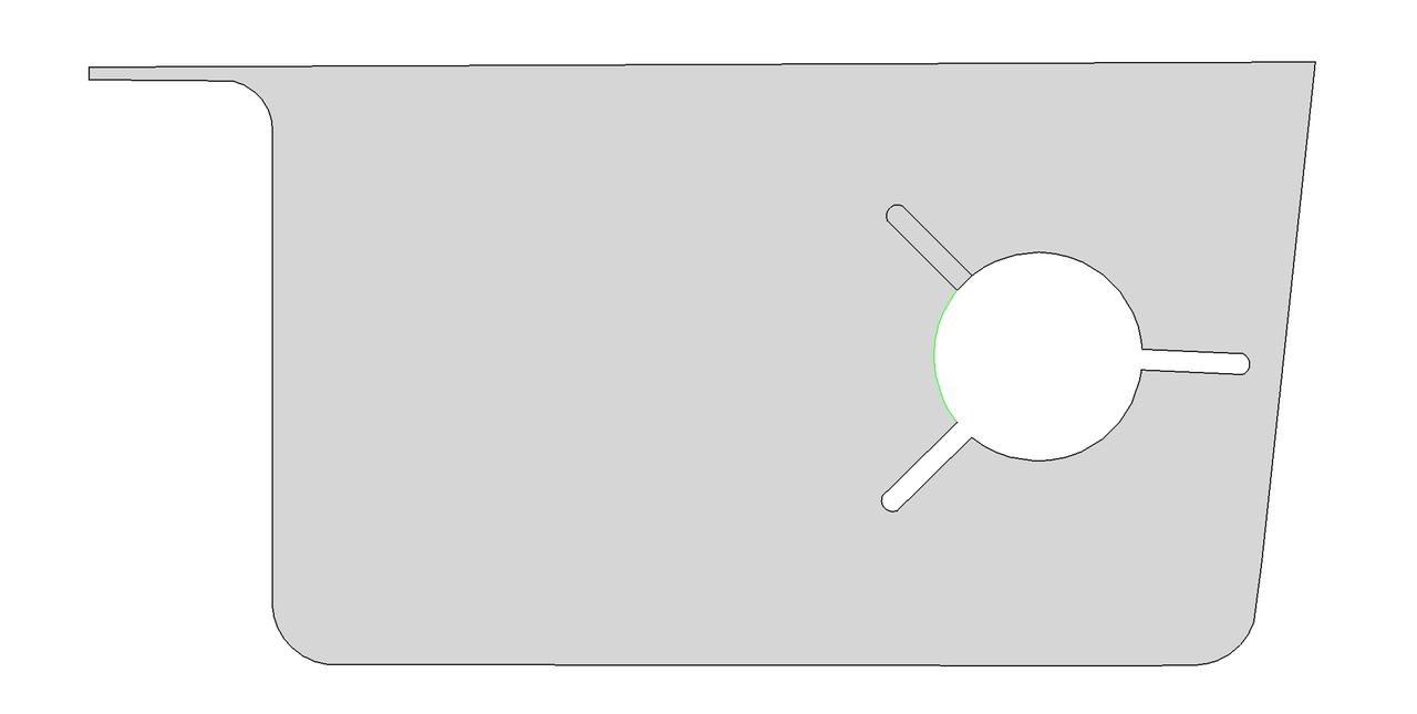
As shown in the figure, the green edge is selected for detection. The returned EdgeType for this edge is FreeEdge, indicating that this edge is a free edge.
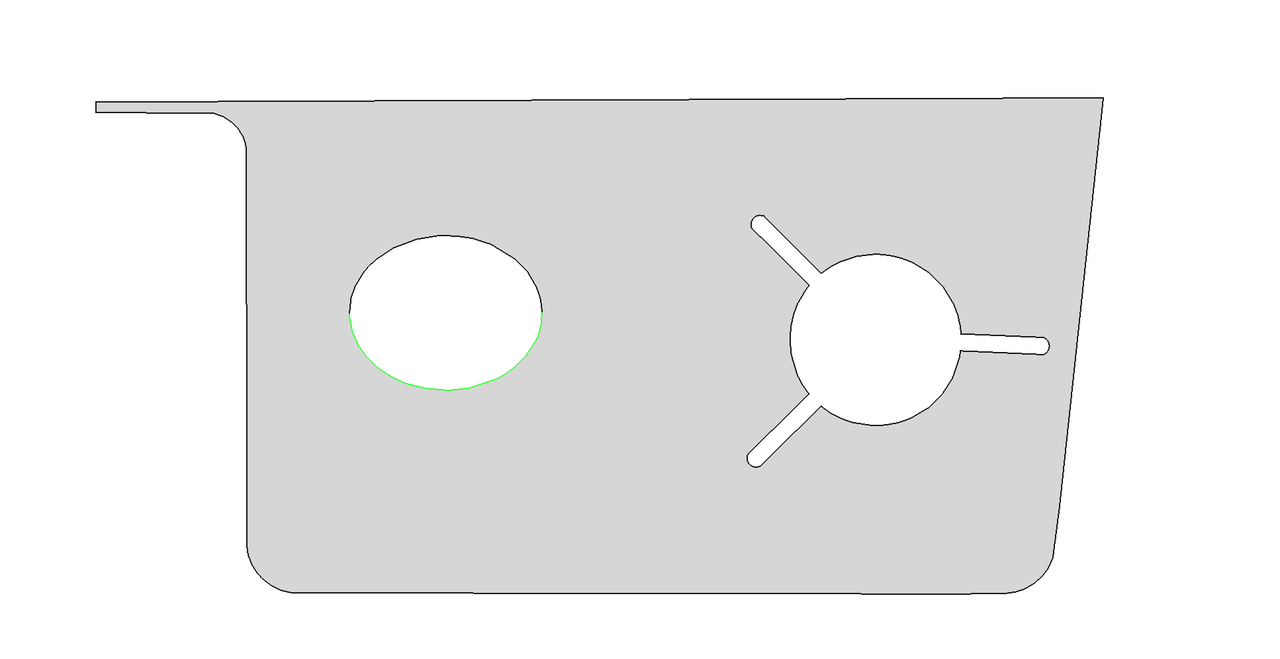
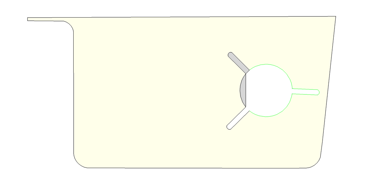
As shown in the figure, the free boundary containing the edge is detected.
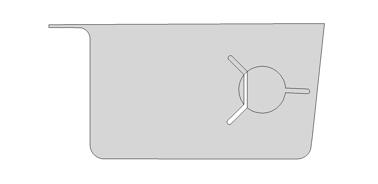
As shown in the figure, the hole bounded by the free boundary has been filled.
As shown in the figure, the green edges are selected as a set to construct a new plane.
As shown in the figure, the Coons Surface has been successfully constructed.
As shown in the figure, the green edges are selected as a set to construct a new plane.
As shown in the figure, the plane has been successfully constructed.

As shown in the figure, the green edges are selected as a set to create a new face based on the surface of the yellow face.
As shown in the figure, the new face has been successfully created.
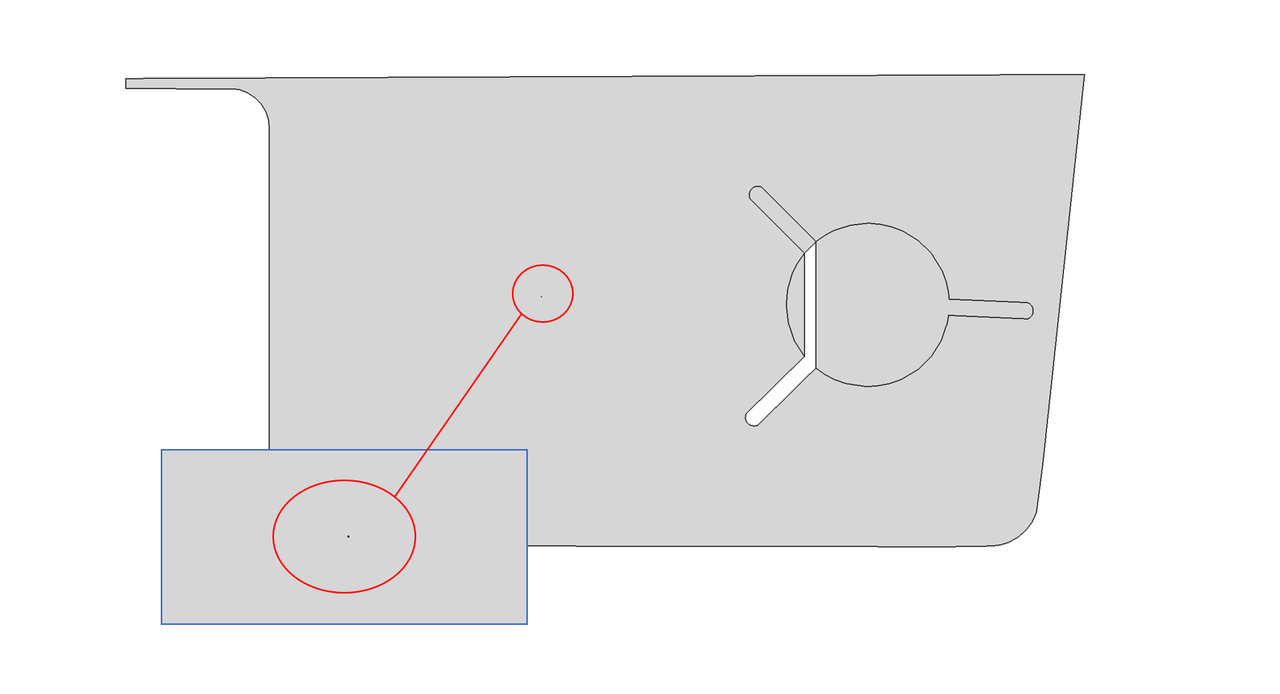
As shown in the figure, the point has been successfully projected onto the face.
Click here example02 to get the full source code of the geometry edit example two. Everyone can download it as needed.
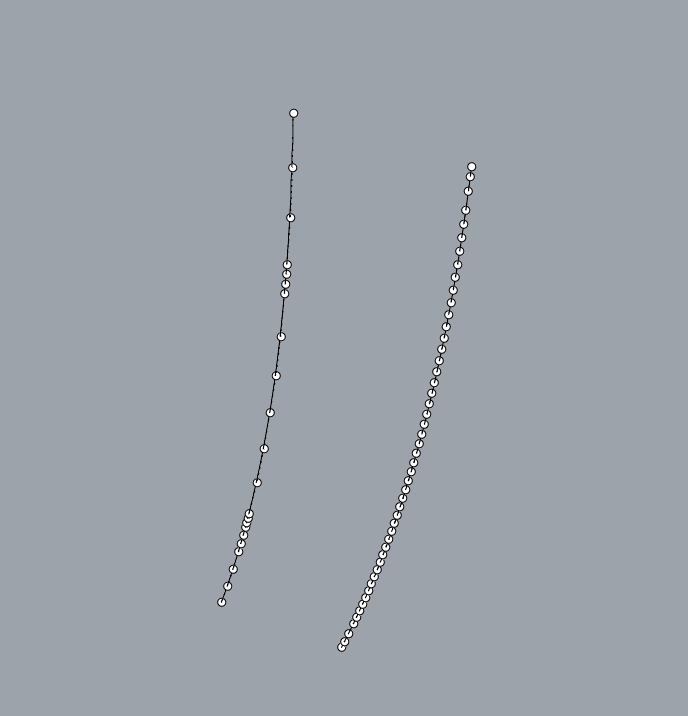
Import a BREP format CAD model as shown in the following images. The left image is the initial model 1, and the right image is the initial model 2.
 |  |
In this tutorial, the example first reads in a BREP model, then performs geometric editing operations on the input model, and finally writes the model into a BREP file.
Import the CAD file and construct the model.
Write the BREP.
The initial model 1 consists of two solids, with the faces of the first solid having inconsistent orientations.
 |  |
As shown in the image below, after performing face orientation alignment on the first solid, the normal vectors of all faces are directed outward.
Check if the shell of the first solid is closed, return true.
As shown in the image below, the second solid has been imprinted with some topological structures.
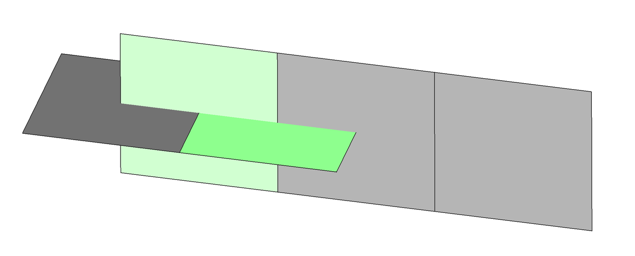
As shown in the image below, select the green face for geometric imprinting.
As shown in the image below, the imprint was successful.
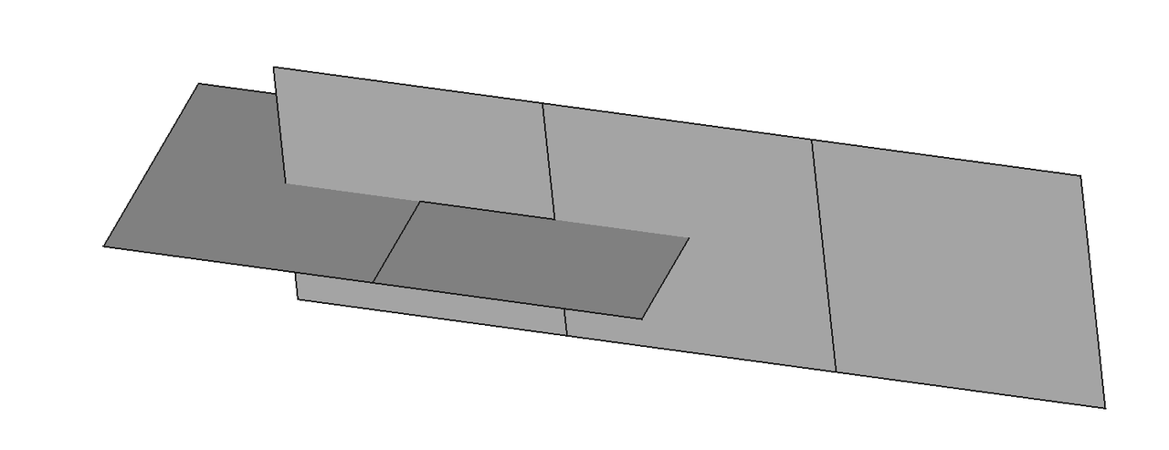
As shown in the image below, select the green face for geometric imprinting.
As shown in the image below, the imprint was successful.
Click here example03 to get the full source code of the geometry edit example three. Everyone can download it as needed.