AMCAX Kernel
Geometry kernel for CAD/CAE/CAM
|
AMCAX Kernel 1.0.0.0
|
|
AMCAX Kernel 1.0.0.0
|
Boundary Representation (BRep) is currently the most popular data structure. BRep can maintain completeness and unambiguity while reducing storage requirements. BRep uses points, curves, and surfaces on the boundaries of entities to represent those entities, and the volume information of the entity is derived from the three-dimensional space enclosed within the boundary. Its two basic elements are: geometric information (Point, Curve, Surface); and topological information (Vertex, Edge, Face connectivity).
Let’s first define the various levels of topological structures in a BRep:
Here are some examples to help you better understand the concept.
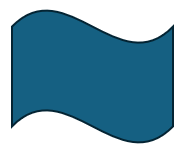
It’s easy to see that this example consists of 4 Vertices, 4 Edges, 1 Wire, and 1 Face.
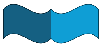
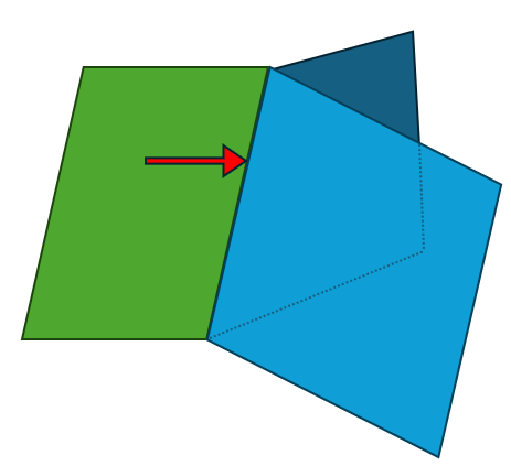
Since the overlapping vertices and edges in the middle are shared, this example consists of 6 Vertices, 7 Edges, 2 Wires, 2 Faces, and 1 Shell.
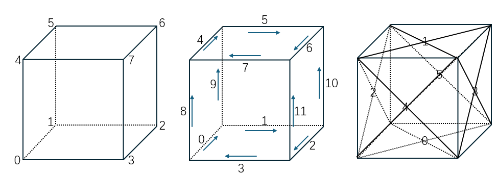
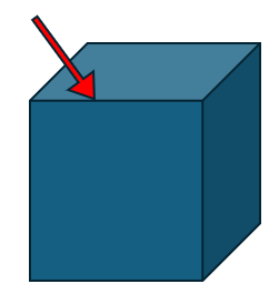
This example consists of 8 Vertices, 12 Edges, 6 Wires, 6 Faces, and 1 Shell.

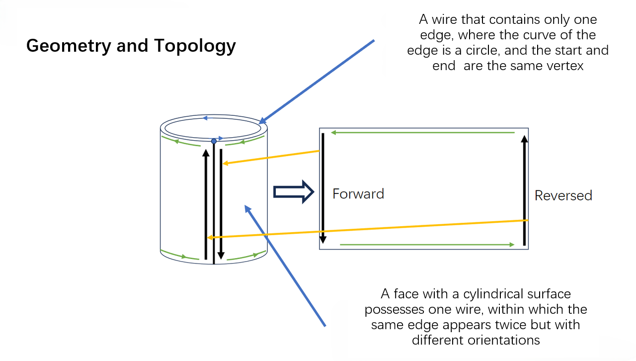
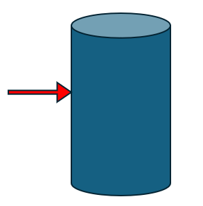
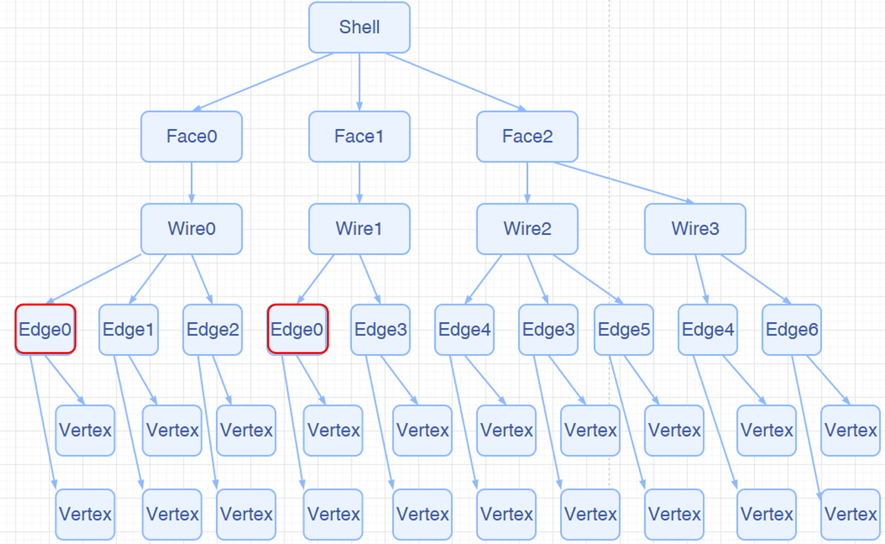
This example consists of 2 Vertices, 3 Edges, 3 Wires, 3 Faces, and 1 Shell. Edge 0 is reused in the Wire, making it a classic Seam Edge.
 |  |
This example consists of 2 Vertices, 3 Edges, 1 Wire, 1 Face, and 1 Shell. In this case, there is not only a Seam Edge but also two Edges with no length. Despite having no length in 3D, these two Edges do have length in the parametric domain, making them classic Degenerated Edges.
Next, we will introduce some common types of Edges.
In a closed TopoShape (like a Shell or Solid), the most common Edge is an edge that is adjacent to two different Faces. An ordinary Edge belongs to two different Faces and has a non-zero length.
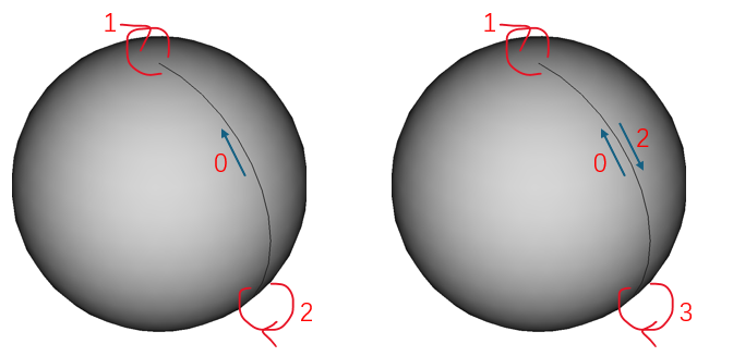
A common special case is the side edge of a cylinder. This Edge is owned by one Face and appears twice in the same Wire of that Face (once forward, once backward). Seam Edges are valid.
A common special case is the top edge of a sphere. This Edge has zero length and degenerates into a point. Degenerated Edges are valid.

An Edge that belongs to only one Face and appears only once in that Face’s Wire is called a Free Edge. Free Edges are invalid in a closed TopoShape.

An Edge that belongs to more than two Faces in one Shape or Solid is called a Non-Manifold Edge. Non-Manifold Edges are invalid.
Let’s first introduce the tree structure of a TopoShape, as shown below:
Traversing a topological structure is a common operation. Our kernel provides two ways: AMCAX::TopoExplorer and AMCAX::WireExplorer. Let’s introduce both methods one by one.
AMCAX::TopoExplorer can traverse through specified types (Shape, Compound, CompSolid, Solid, Shell, Face, Wire, Edge, Vertex) within a TopoShape in a preorder manner, based on its tree structure, to find child shapes of the specified type. For example, to traverse the Faces of a TopoShape, you can use the following code:
It’s important to note that AMCAX::TopoExplorer does not consider duplicates (level of "equality"). That is, if an Edge is shared by two Faces, AMCAX::TopoExplorer will traverse this Edge twice. If you don’t want to traverse it twice, you can use a std::unordered_set to remove duplicates, like this:
In the above, we discussed duplication, which inherently implies the definition of "equality". Next, we will introduce the three levels of "equality" for TopoShape, with increasing strictness:
It's not difficult to realize that when we need to traverse the edges of a Wire in order, AMCAX::TopoExplorer cannot actually meet the demand. However, AMCAX::WireExplorer can fulfill this requirement, though the traversal speed will decrease.
Due to the tree structure and pre-order traversal, each Edge (similarly for Vertex, Wire, and Face) actually has its own index. The AMCAX::TopoExplorerTool class provides some convenient traversal operations. AMCAX::TopoExplorerTool::MapShapes can get an ordered set of indices for a specific type of topological structure (such as Edge), and the resulting set is unique.
In fact, this index matches the one shown in the lower-left corner of FreeCAD (FreeCAD starts from 1, while our kernel starts from 0).
AMCAX::TopoExplorerTool::MapShapesAndAncestors can retrieve a map from child shapes to their corresponding parent shapes, while AMCAX::TopoExplorerTool::MapShapesAndUniqueAncestors also provides a map. The difference is that when a seam edge is input, MapShapesAndUniqueAncestors will return a single associated face, while MapShapesAndAncestors will return two associated faces. For example, the mapping from Edge to its associated Face can be obtained as follows:
Determining whether an Edge is degenerated is very important. For example, we should not sample along a degenerated edge. We can use AMCAX::TopoTool::Degenerated to check.
You can determine whether an Edge is a seam edge using AMCAX::TopoTool::IsClosed.
Quickly creating topological structures is a basic requirement, and functions like AMCAX::MakeVertex, AMCAX::MakeEdge, AMCAX::MakeWire, AMCAX::MakeFace, etc., provide quick creation methods for different topological structures. These are commonly used and important functionalities.
A Vertex can be created with a Point3:
AMCAX::MakeEdge can quickly create an Edge based on a Curve. If no Vertex is provided in the input for MakeEdge, it will automatically create two Vertices. This means that if you want to create two connected Edges using MakeEdge, you must pay attention to the shared Vertex. A simple construction will result in two Edges and four Vertices. Additionally, degenerated edges can also be created using MakeEdge. MakeEdge has many functionalities, and we will introduce them categorically:
You can create a line segment Edge using two Point3s or two TopoVertices. Note that the distance between the two Point3s/TopoVertices must be greater than AMCAX::Precision::Confusion(), otherwise, they will be considered the same Point3/TopoVertex.
For example, you can build it based on Line3, Circle3, etc. Here’s an example using Line3:
MakeEdge will automatically adjust parameters, Point3, and Vertex order based on the mathematical expression:
This is an important functionality for building Edges from curves. Here, MakeEdge will still automatically adjust parameters, Point3, and Vertex order, as well as Vertex orientation.
It is important to note that Edges created based on pcurve and Surface do not have 3D curves. Here's how you can construct them:
A wire can be constructed in the following two ways:
Note: Each edge added must geometrically connect to the wire that has already been added. For the example above, if the edges are added in the order e1—e3—e2—e4, when e3 is added, it will fail because it is not connected to e1. In this case, calling IsDone() will return false, and calling Error() will return WireError::DisconnectedWire. If it is known that the edges to be connected into a wire are connected, but the exact connection order is unknown, then the edge list method described below should be used.
The order of edges in the list will not affect the result of the wire construction.
Note: MakeWire can construct a wire that does not contain Seam Edges or degenerate edges. It supports adding individual edges or an edge list. MakeWire cannot correctly construct a wire containing degenerate edges because it determines orientation based on the 3D positions of the vertices, and degenerate edges have identical vertices, which may result in incorrect orientation. MakeWire also cannot correctly construct a wire containing non-manifold vertices, as this interface requires that the degree of vertices within a wire must be 2 (or 1, for open wire endpoints).
AMCAX::MakeFace has many functionalities, which we will introduce categorically:
t can be constructed based on mathematical expressions such as Plane, Cylinder, etc.:
Constructing a face from a Geom3Surface is the most common functionality of MakeFace:
MakeFace requires providing tolerance when providing a surface. It is important to note that if the input surface is infinite and there are no constrained parameter ranges, a wire will not be automatically generated. In other cases, a wire will be generated automatically.
When the wire lies on a plane, a face can be successfully constructed by directly inputting the wire:
Note: Inputting a wire that does not lie on a plane may result in failure.
Note: The final boolean parameter indicates whether the face region is inside the wire (true means inside).
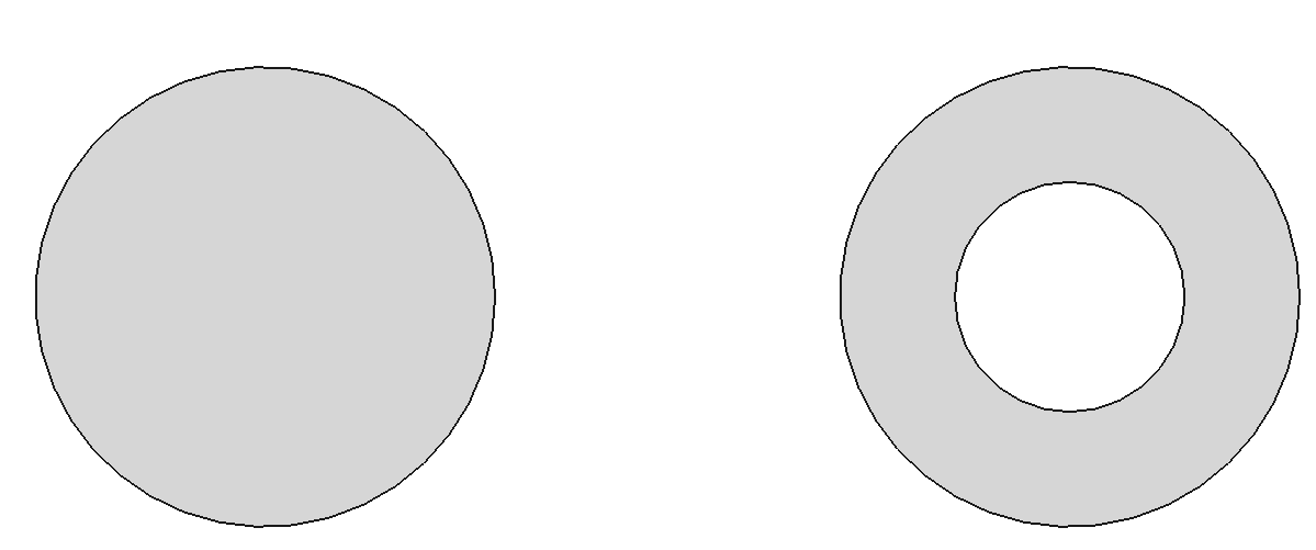
Adding a wire to an existing face:
After execution, the result is as shown in the figure below: the left side is face7, and the right side is face8.
However, it is important to note the orientation of the wire. For example, if the code is written as below, it will produce an incorrect result:
The correct approach is to set the orientation of the edge or wire to Reversed at the edge or wire level.