|
AMCAX Kernel 1.0.0.0
|
|
AMCAX Kernel 1.0.0.0
|
Quickly creating topological structures is a basic requirement, and functions like AMCAX::MakeVertex, AMCAX::MakeEdge, AMCAX::MakeWire, AMCAX::MakeFace, etc., provide quick creation methods for different topological structures. These are commonly used and important functionalities.
A Vertex can be created with a Point3:
AMCAX::MakeEdge can quickly create an Edge based on a Curve. If no Vertex is provided in the input for MakeEdge, it will automatically create two Vertices. This means that if you want to create two connected Edges using MakeEdge, you must pay attention to the shared Vertex. A simple construction will result in two Edges and four Vertices. Additionally, degenerated edges can also be created using MakeEdge. MakeEdge has many functionalities, and we will introduce them categorically:
You can create a line segment Edge using two Point3s or two TopoVertices. Note that the distance between the two Point3s/TopoVertices must be greater than AMCAX::Precision::Confusion(), otherwise, they will be considered the same Point3/TopoVertex.
For example, you can build it based on Line3, Circle3, etc. Here’s an example using Line3:
MakeEdge will automatically adjust parameters, Point3, and Vertex order based on the mathematical expression:
This is an important functionality for building Edges from curves. Here, MakeEdge will still automatically adjust parameters, Point3, and Vertex order, as well as Vertex orientation.
It is important to note that Edges created based on pcurve and Surface do not have 3D curves. Here's how you can construct them:
A wire can be constructed in the following two ways:
Note: Each edge added must geometrically connect to the edge that has already been added. For the example above, if the edges are added in the order e1—e3—e2—e4, when e3 is added, it will fail because it is not connected to e1. In this case, calling IsDone() will return false, and calling Error() will return WireError::DisconnectedWire. If it is known that the edges to be connected into a wire are connected, but the exact connection order is unknown, then the edge list method described below should be used.
The order of edges in the list will not affect the result of the wire construction.
Note: MakeWire can construct a wire that does not contain Seam Edges or degenerate edges. It supports adding individual edges or an edge list. MakeWire cannot correctly construct a wire containing degenerate edges because it determines orientation based on the 3D positions of the vertices, and degenerate edges have identical vertices, which may result in incorrect orientation. MakeWire also cannot correctly construct a wire containing non-manifold vertices, as this interface requires that the degree of vertices within a wire must be 2 (or 1, for open wire endpoints).
When adding a wire, its first edge must connect to the existing wire; otherwise the operation will fail.
In this example, if edge4 is added to the existing wire before adding wire567, calling IsDone() will return false and Error() will return WireError::DisconnectedWire.
AMCAX::MakeFace has many functionalities, which we will introduce categorically:
t can be constructed based on mathematical expressions such as Plane, Cylinder, etc.:
Constructing a face from a Geom3Surface is the most common functionality of MakeFace:
MakeFace requires providing tolerance when providing a surface. It is important to note that if the input surface is infinite and there are no constrained parameter ranges, a wire will not be automatically generated. In other cases, a wire will be generated automatically.
When the wire lies on a plane, a face can be successfully constructed by directly inputting the wire:
Note: Inputting a wire that does not lie on a plane may result in failure.
Note: The final boolean parameter indicates whether the face region is inside the wire (true means inside).
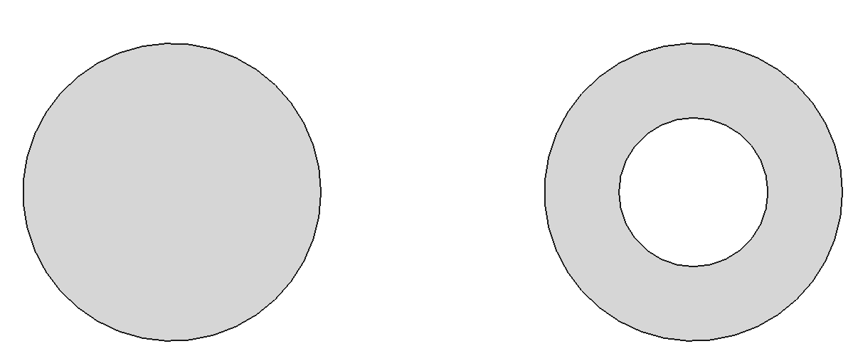
Adding a wire to an existing face:
After execution, the result is as shown in the figure below: the left side is face7, and the right side is face8.
However, it is important to note the orientation of the wire. For example, if the code is written as below, it will produce an incorrect result:
The correct approach is to set the orientation of the edge or wire to Reversed at the edge or wire level.
Although Make*.hpp provides some convenient APIs for building TopoShapes, certain modeling problems can only be solved by TopoBuilder. In this section, we will introduce the methods for constructing different topological structures using TopoBuilder.
AMCAX::TopoBuilder::MakeVertex provides functionality to create a vertex.
There are different methods to build different types of edges. We will introduce them one by one:
The usual modeling approach is to calculate all the required Points, Curve3d, and PCurve using geometry, then build the topological structure:
Step 1: Prepare the Curve3d and construct the Edge using the curve.
AMCAX::TopoBuilder::Range sets the parameter range for the TopoEdge. If the parameter range of the curve matches the expected range of the edge, this step can be skipped.
Step 2: Prepare the start and end vertices and add them to the edge.
Note: Pay attention to the orientation of the start and end vertices. The orientation of the starting vertex is Forward, and the ending vertex is Reversed. The default orientation is Forward, so you need to change the orientation of the end vertex. There are two ways to do this: modify the orientation of the vertex itself or create a new one without modifying the original vertex. AMCAX::TopoShape::SetOrientation and AMCAX::TopoShape::Reverse modify the original vertex, while AMCAX::TopoShape::Oriented creates a new one and passes it to the builder.
Step 3: After constructing the Face, add the pcurve:
The direction of the pcurve should be consistent with the curve3d. The orientation of the edge does not affect the direction of the pcurve. Remember: "Geometry is geometry, topology is topology." The process of adding vertices can occur after creating the edge, so swapping steps 2 and 3 is fine. Adding vertices before calling Range is also acceptable.
The steps are mostly the same, but with a slight variation in step 3:
Note: The directions of pcurve1 and pcurve2 must remain consistent with the curve3d. pcurve1 corresponds to the Forward edge in the surface parameter domain, while pcurve2 corresponds to the Reversed edge in the surface parameter domain.
Other steps are the same, but step 1 is different, as there is no curve3d:
Make sure to set the degenerated flag to True. The direction of the pcurve does not need to match the curve3d, just the orientation of the edge.
The steps remain the same, but step 3 differs, where only one pcurve is used.
The standard approach is:
Step 1: Determine the direction of the Wire based on the parameter domain, and identify which edges to use and their orientations:
Step 2: Construct the Wire and add the edges:
The order in which edges are added can be arbitrary.
Step 3: Set the closed flag for the Wire:
To create a face, use the following method:
When constructing a shell, be mindful of the closed flag. The method is as follows:
To construct a solid, use this method:
To create a compound, use this method: