|
AMCAX Kernel 1.0.0.0
|
|
AMCAX Kernel 1.0.0.0
|
Boundary Representation (B-rep) is currently the most popular data structure. B-rep can maintain completeness and unambiguity while reducing storage requirements. B-rep uses points, curves, and surfaces on the boundaries of entities to represent those entities, and the volume information of the entity is derived from the three-dimensional space enclosed within the boundary. Its two basic elements are: geometric information (Point, Curve, Surface); and topological information (Vertex, Edge, Face connectivity).
Let’s first define the various levels of topological structures in a B-rep:
Here are some examples to help you better understand the concept.
It’s easy to see that this example consists of 4 Vertices, 4 Edges, 1 Wire, and 1 Face.
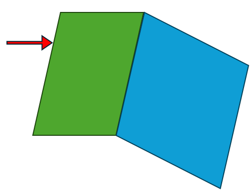
Since the overlapping vertices and edges in the middle are shared, this example consists of 6 Vertices, 7 Edges, 2 Wires, 2 Faces, and 1 Shell.
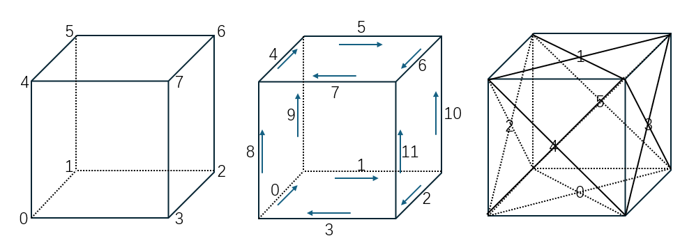
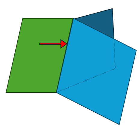
This example consists of 8 Vertices, 12 Edges, 6 Wires, 6 Faces, and 1 Shell.
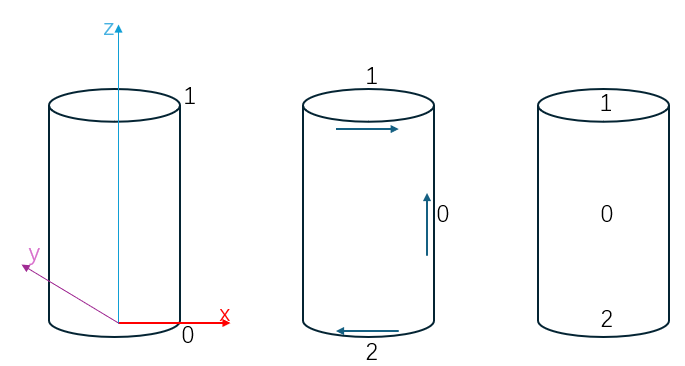
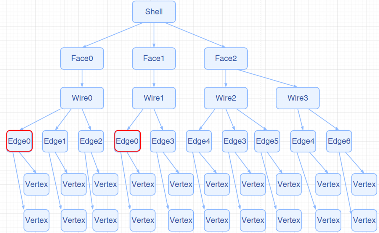
This example consists of 2 Vertices, 3 Edges, 3 Wires, 3 Faces, and 1 Shell. Edge 0 is reused in the Wire, making it a classic Seam Edge.
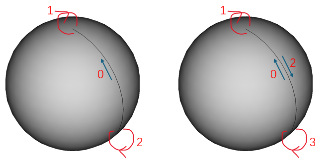 |  |
This example consists of 2 Vertices, 3 Edges, 1 Wire, 1 Face, and 1 Shell. In this case, there is not only a Seam Edge but also two Edges with no length. Despite having no length in 3D, these two Edges do have length in the parametric domain, making them classic Degenerated Edges.
Next, we will introduce some common types of Edges.
In a closed TopoShape (like a Shell or Solid), the most common Edge is an edge that is adjacent to two different Faces. An ordinary Edge belongs to two different Faces and has a non-zero length.
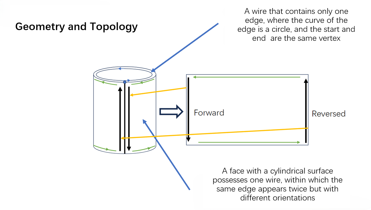
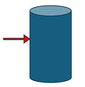
A common special case is the side edge of a cylinder. This Edge is owned by one Face and appears twice in the same Wire of that Face (once forward, once backward). Seam Edges are valid.
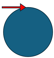
A common special case is the top edge of a sphere. This Edge has zero length and degenerates into a point. Degenerated Edges are valid.
An Edge that belongs to only one Face and appears only once in that Face’s Wire is called a Free Edge. Free Edges are invalid in a closed TopoShape.
An Edge that belongs to more than two Faces in one Shape or Solid is called a Non-Manifold Edge. Non-Manifold Edges are invalid.
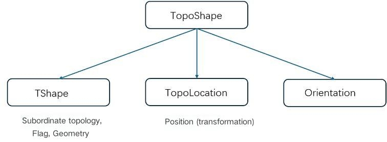
Let’s first introduce the tree structure of a TopoShape, as shown below:
Traversing a topological structure is a common operation. Our kernel provides two ways: AMCAX::TopoExplorer and AMCAX::WireExplorer. Let’s introduce both methods one by one.
AMCAX::TopoExplorer can traverse through specified types (Shape, Compound, CompSolid, Solid, Shell, Face, Wire, Edge, Vertex) within a TopoShape in a preorder manner, based on its tree structure, to find child shapes of the specified type. For example, to traverse the Faces of a TopoShape, you can use the following code:
It’s important to note that AMCAX::TopoExplorer does not consider duplicates (level of "equality"). That is, if an Edge is shared by two Faces, AMCAX::TopoExplorer will traverse this Edge twice. If you don’t want to traverse it twice, you can use a std::unordered_set to remove duplicates, like this:
In the above, we discussed duplication, which inherently implies the definition of "equality". Next, we will introduce the three levels of "equality" for TopoShape, with increasing strictness:
When sequential traversal of edges in a Wire is required (where the end vertex of one edge matches the start vertex of the next), AMCAX::TopoExplorer may not meet this requirement. For example, when constructing three edges from three Point3 objects and combining them into a Wire, if the edges are added in an order inconsistent with their actual connectivity, TopoExplorer will return edges in their construction order rather than topological connection order. In such cases, AMCAX::WireExplorer should be used instead, which guarantees traversal following the actual edge connectivity sequence – though with slower performance.
Due to the tree structure and pre-order traversal, each Edge (similarly for Vertex, Wire, and Face) actually has its own index. The AMCAX::TopoExplorerTool class provides some convenient traversal operations. AMCAX::TopoExplorerTool::MapShapes can get an ordered set of indices for a specific type of topological structure (such as Edge), and the resulting set is unique.
In fact, this index matches the one shown in the lower-left corner of FreeCAD (FreeCAD starts from 1, while our kernel starts from 0).
AMCAX::TopoExplorerTool::MapShapesAndAncestors can retrieve a map from child shapes to their corresponding parent shapes, while AMCAX::TopoExplorerTool::MapShapesAndUniqueAncestors also provides a map. The difference is that when a seam edge is input, MapShapesAndUniqueAncestors will return a single associated face, while MapShapesAndAncestors will return two associated faces. For example, the mapping from Edge to its associated Face can be obtained as follows:
Determining whether an Edge is degenerated is very important. For example, we should not sample along a degenerated edge. We can use AMCAX::TopoTool::Degenerated to check.
You can determine whether an Edge is a seam edge using AMCAX::TopoTool::IsClosed.
A Vertex contains only one Point, representing a point in 3D space. The method to access the Point from a Vertex is AMCAX::TopoTool::Point :
curve3d is a 3D parametric curve. pcurve is a 2D parametric curve. pcurve is bound to <Edge, Surface, Location>, meaning Edge, Surface, and Location are the indexes of a pcurve.
An Edge typically has one curve3d and two pcurves. In fact, a 3D parametric curve can also be constructed using a pcurve and surface, but due to tolerance, the two resulting 3D parametric curves will not coincide with the curve3d. In geometric modeling, there is no requirement for the number of curves in an Edge; it is fine if there are no curves. However, unless in special cases, the final geometric model should include one curve3d and two pcurves.
Next, let's introduce some special cases:
If the Edge lies on a plane (Geom3Plane), no additional pcurve is needed, because the Edge on the plane can be directly represented by a curve3d.
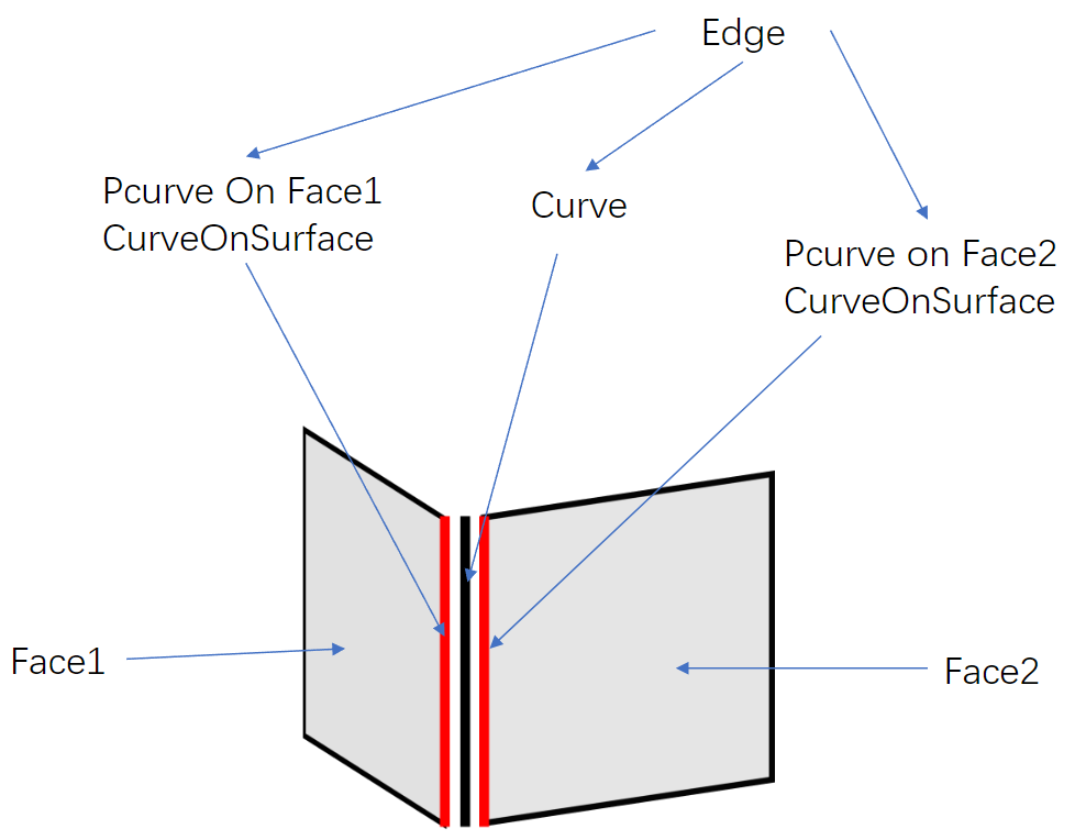
A Seam Edge has one curve3d and two pcurves, both on one Face. The difference between the two pcurves lies in the Orientation of the Edge: one pcurve corresponds to the forward direction of the Edge, and the other corresponds to the reverse direction.
A Degenerated Edge has only one pcurve, with no curve3d.
A Free Edge has one curve3d and one pcurve.
It is important to note that the kernel does not provide functionality for calculating a pcurve from a curve3d. The correct modeling approach is to first construct the pcurve and then use the pcurve and surface to calculate the curve3d:
The method to access the Curve3d of an Edge is AMCAX::TopoTool::Curve :
There are a few points to note:
1.The interface returns the raw curve. If an Edge is a segment formed by a Geom3Line and two Vertices, this interface will return an infinitely long line (Geom3Line), with fp and lp being the parameters of the two Vertices on the curve.
2.AMCAX::TopoTool::Curve has an overloaded function, one that takes a loc input and one that does not. The interface with loc returns a pointer to the curve memory inside the edge, while the interface without loc, when the edge's location is null, returns a pointer to the memory; otherwise, it returns a pointer to a newly constructed curve.
3.If the input is a degenerated edge, a null pointer will be returned.
4.The interface with loc returns a Curve with an additional location compared to the actual location, and applying location.Transformation() directly on the Curve is prohibited, as this will alter the edge's content. The correct approach is to copy the Curve and then apply transformations to the CopyCurve:
The method to access the pcurve is AMCAX::TopoTool::CurveOnSurface :
It is important to note that if the input is a seam edge, special handling is required. Depending on the Edge's Orientation, different pcurves will be returned:
In the above example, two pcurves for the seam edge of a cylinder were obtained. The orientation of these two pcurves is always consistent and matches the orientation of the curve3d. The edge's orientation is not considered.
A Face contains only one Surface. The method to access the Surface is AMCAX::TopoTool::Surface:
The interface with loc returns a Surface with an additional location compared to the actual location, and applying location.Transformation() directly on the Surface is prohibited, as this will alter the face's content. The correct approach is to copy the Surface and then apply transformations to the CopySurface:
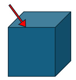
Mesh refers to a triangular mesh. The significance of Mesh in CAD is for rendering. Since the basic drawing elements in OpenGL are points, line segments, and triangles, curves must be discretized into polygons for rendering, and surfaces must be discretized into Mesh for rendering. Therefore, in applications with a graphical user interface (GUI), the BRep model that is seen is typically visualized through a triangular mesh. As shown in the figure below.
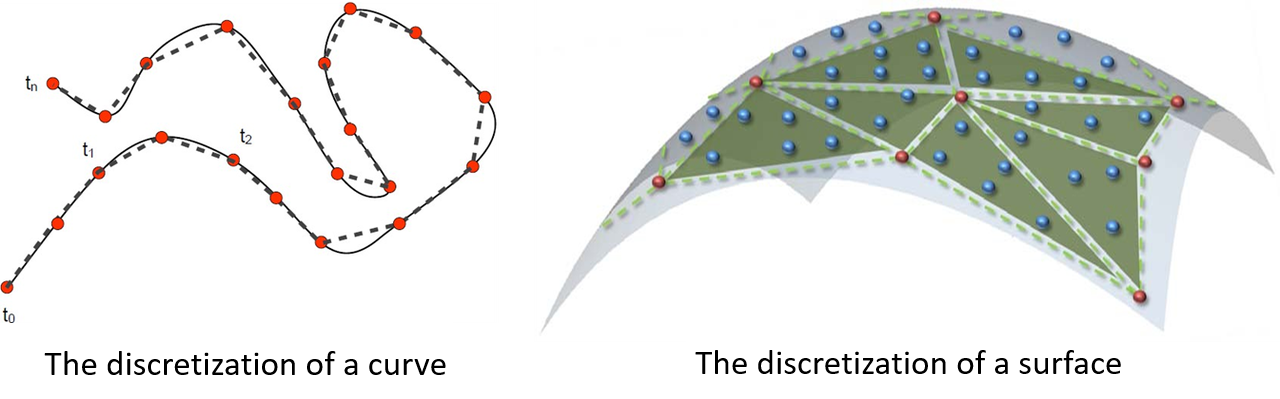
Clearly, discretization introduces errors, meaning that the BRep model displayed in applications with a GUI is not the model itself, but rather its Mesh. The error between the two is determined by the discretization precision, which is the density of the mesh. Considering that Mesh generation in CAD models must be very fast, the precision of the Mesh is understandably not very high.
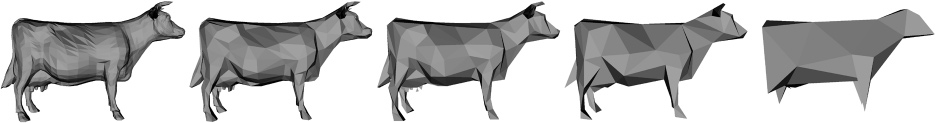
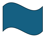
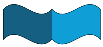
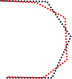
There are many issues caused by discretization, such as visually judging whether two identical circles overlap or whether two identical spheres overlap, which can lead to situations like the one shown in the image below. Another issue is rendering a smooth surface as if it has wrinkles. Another type of problem is mesh generation failure, which can cause holes to appear. Therefore, when holes are seen in the model, one needs to consider both the Mesh reasons and the model itself.
Next, we will introduce the generation, retrieval, and read/write methods of Mesh.
Although Mesh is necessary for rendering, it is not always required to use the kernel to generate Mesh for the model after it is constructed, because software with a GUI will generate the Mesh automatically for rendering. Normals in rendering are crucial information. If the Mesh does not provide normals, an approximate normal will be automatically calculated based on the Mesh during rendering. If it is necessary to ensure that the normals of the triangular mesh match those of the CAD model, the AMCAX::MakeShapeTool::EnsureNormalConsistency() can be used.